
Multi-station liquid injection system for capacitor manufacturing

A multi-station, capacitor technology, applied in the field of capacitors, can solve the problems of electrolyte leakage, unstable feeding, capacitor dumping, etc., and achieve the effect of avoiding dumping and leakage

Active Publication Date: 2020-10-23
苏州市凯瑞达电容器制造有限公司
View PDF5 Cites 1 Cited by
  • Summary
  • Abstract
  • Description
  • Claims
  • Application Information

AI Technical Summary

Problems solved by technology

[0004] The purpose of the present invention is to provide a multi-station liquid injection system for capacitor manufacturing, so as to solve the problem that in the prior art, the method of dropping directly on the conveyor belt through the opening can easily lead to unstable blanking, capacitor dumping, and electrolyte leakage the problem of the situation

Method used


Image

  • Multi-station liquid injection system for capacitor manufacturing
  • Multi-station liquid injection system for capacitor manufacturing
  • Multi-station liquid injection system for capacitor manufacturing

Examples


Embodiment Construction

[0020] In order to make the purpose, technical solutions and advantages of the embodiments of the present invention clearer, the technical solutions in the embodiments of the present invention will be clearly and completely described below in conjunction with the accompanying drawings in the embodiments of the present invention. Obviously, the described embodiments It is some embodiments of the present invention, but not all of them. Based on the implementation manners in the present invention, all other implementation manners obtained by persons of ordinary skill in the art without creative efforts fall within the protection scope of the present invention. Accordingly, the following detailed description of the embodiments of the invention provided in the accompanying drawings is not intended to limit the scope of the claimed invention, but merely represents selected embodiments of the invention. Based on the implementation manners in the present invention, all other implement...


PUM


Abstract

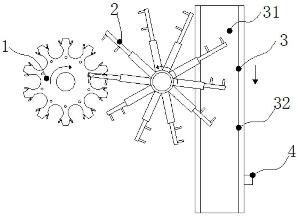
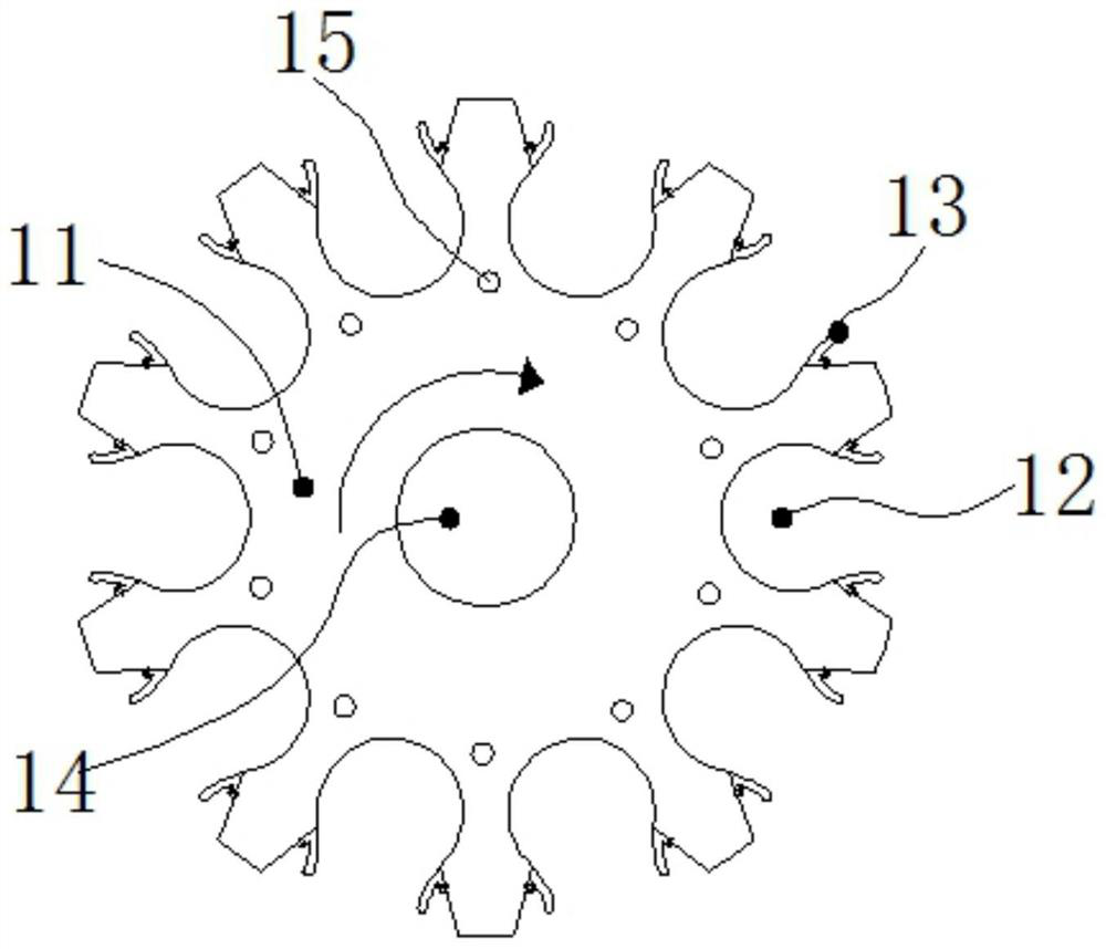
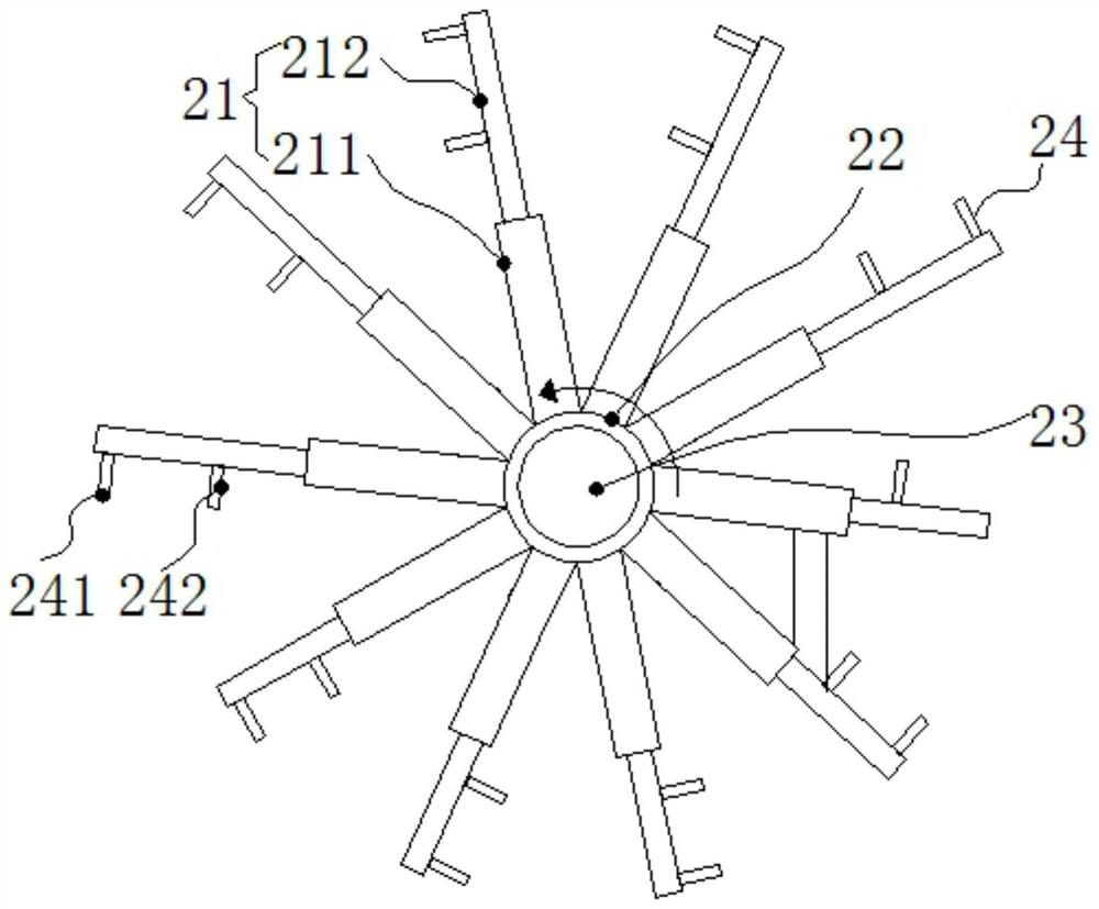
The invention discloses a multi-station liquid injection system for capacitor manufacturing. The liquid injection station comprises a liquid injection station main body and a programmable logic controller (PLC), the liquid injection station main body comprises a turntable; equidistant accommodating openings with openings are formed in the outer edge of the turntable; and elastic plastic arc piecesare fixed to the two sides of the openings of the accommodating openings with the openings. Grooves are formed in the upper surface of the rotary disc at equal intervals. The grooves are located between the two accommodating openings with the openings. A discharging device is arranged on one side of the liquid injection station main body; the discharging device comprises a mounting ring; telescopic hydraulic cylinders are mounted on the mounting ring at equal intervals; each telescopic hydraulic cylinder comprises a cylinder body and a piston rod; a capacitor placing station is provided withthe accommodating openings with the openings, the elastic plastic arc pieces can be extruded, the capacitor can be pulled out from the openings after extrusion, the conveying belt and the dischargingdevice with the telescopic hydraulic cylinders and the clamping device are arranged, and when the clamping device can stably discharge the capacitor to the conveying belt.

Description

technical field [0001] The invention relates to the technical field of capacitors, in particular to a multi-station liquid injection system for manufacturing capacitors. Background technique [0002] A kind of electrolytic paper made of Manila fiber is used for isolation and insulation between the positive and negative aluminum plates of the capacitor. However, impurities such as burrs and foil dust between the positive foil and the negative box will affect the safety and handling of the capacitor. In the past, the electrolyte was mainly impregnated by vacuum or pressurization. The traditional impregnation electrolyte needs to bring cross-contamination and excessive electrolyte waste; [0003] For this reason, a patent application number of 201821615054.9 is proposed. We propose a liquid injection system for capacitors to solve the above problems. A multi-station liquid injection system for capacitor manufacturing. Station, and a total of multiple liquid injection heads are...

Claims


Application Information

Patent Timeline
Patent Type & Authority Applications(China)
IPC IPC(8): H01G13/04
CPCH01G13/04
Inventor 蒋建忠陈韶波
Owner 苏州市凯瑞达电容器制造有限公司
Learn More