
Wafer etching method

A wafer and dry etching technology, which is applied in the manufacture of discharge tubes, electrical components, semiconductors/solid-state devices, etc., can solve problems affecting the uniformity of etching, contamination of etching equipment, and affecting the etching morphology of wafers, etc.

Active Publication Date: 2020-10-23
北京智创芯源科技有限公司
View PDF17 Cites 1 Cited by
  • Summary
  • Abstract
  • Description
  • Claims
  • Application Information

AI Technical Summary

Problems solved by technology

During the etching process, there are the following problems: (1) The plasma will continuously etch the part of the graphite tray that does not cover the wafer, resulting in poor surface flatness of the graphite tray, and the contact between the thermally conductive vacuum grease and the wafer during subsequent use Unevenness leads to differences in the temperature distribution of the wafer surface during etching, which affects the uniformity of etching; (2) When artificial pressure is applied, the thermally conductive vacuum grease overflows around the wafer, and the overflowing thermally conductive vacuum grease reacts with the plasma to produce some polymers , affect the etching morphology of the wafer, and at the same time cause pollution to the etching equipment; (3) it is easy to cause debris when artificial pressure is applied; (4) the cost of the graphite tray is high

Method used


Image

  • Wafer etching method
  • Wafer etching method
  • Wafer etching method

Examples


Embodiment Construction

[0037] In order to enable those skilled in the art to better understand the solution of the present application, the present application will be further described in detail below in conjunction with the drawings and specific implementation methods. Apparently, the described embodiments are only some of the embodiments of this application, not all of them. Based on the embodiments in this application, all other embodiments obtained by persons of ordinary skill in the art without making creative efforts belong to the scope of protection of this application.

[0038] In the following description, a lot of specific details are set forth in order to fully understand the present invention, but the present invention can also be implemented in other ways different from those described here, and those skilled in the art can do it without departing from the meaning of the present invention. By analogy, the present invention is therefore not limited to the specific examples disclosed bel...


PUM


Abstract

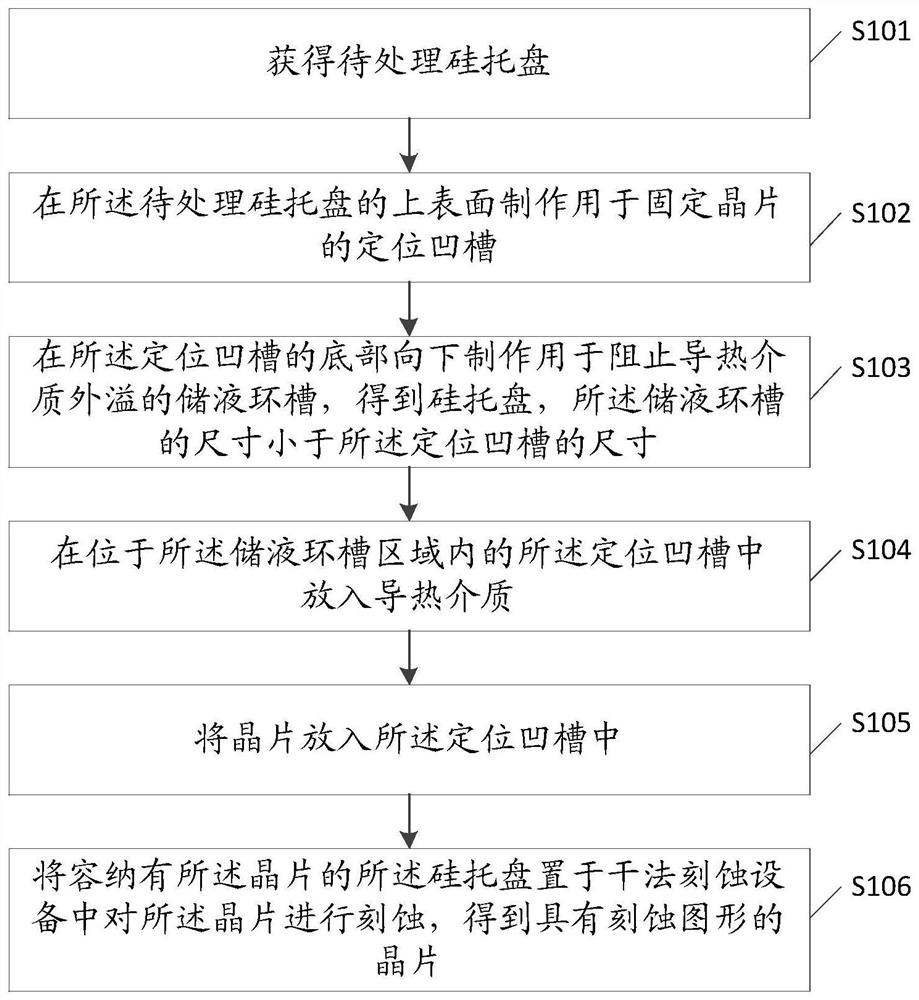
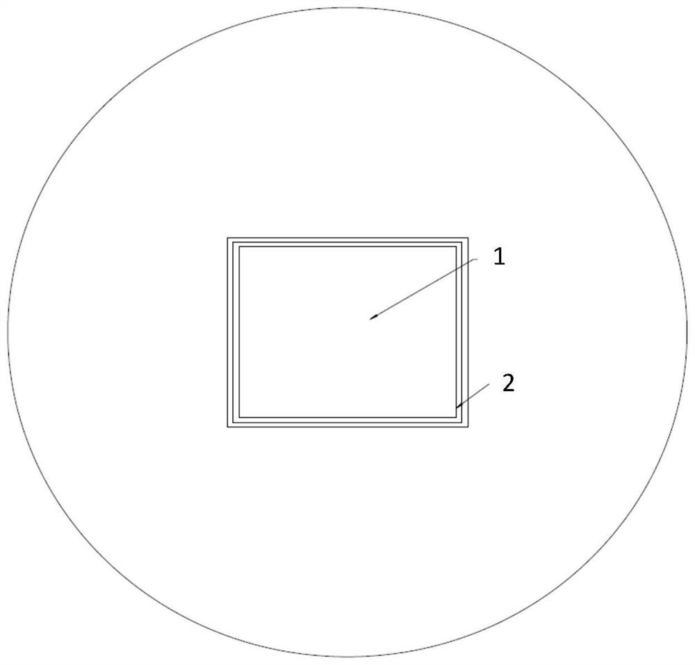
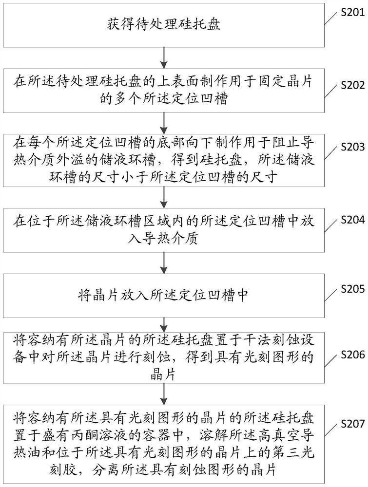
The invention discloses a wafer etching method. The wafer etching method comprises the steps: obtaining a to-be-processed silicon tray; manufacturing a positioning groove for fixing a wafer in the upper surface of the to-be-processed silicon tray; manufacturing a liquid storage annular groove used for preventing the heat conduction medium from overflowing in the bottom of the positioning groove, and obtaining a silicon tray, wherein the size of the liquid storage annular groove is smaller than that of the positioning groove; putting a heat-conducting medium into the positioning groove positioned in the liquid storage annular groove area; putting the wafer into the positioning groove; and placing the silicon tray containing the wafer in dry etching equipment to etch the wafer to obtain thewafer with an etching pattern. The silicon tray with the positioning groove and the liquid storage annular groove is manufactured; the silicon tray is low in cost; the liquid storage annular groove isused for preventing the heat-conducting medium from overflowing, so that generation of impurities caused by reaction with the etching gas does not occur; the wafer is contained in the positioning groove, so that the wafer can be prevented from sliding; the wafer does not need to be pressed, so that the fragment rate is reduced; and the area where the wafer is located is not affected, and etchinguniformity is guaranteed.

Description

technical field [0001] The present application relates to the technical field of semiconductors, in particular to a wafer etching method. Background technique [0002] Dry etching is a commonly used technique in the semiconductor processing process. When etching a wafer, it is necessary to place the wafer on a tray and then put it into a plasma etching device for etching. [0003] At present, for infrared material wafers, such as soft and brittle material wafers such as mercury cadmium telluride, graphite trays are used for etching, thermally conductive vacuum grease is coated on the graphite tray, and then the wafer is placed on the thermally conductive vacuum grease, artificially adding a certain amount of heat to the wafer. The pressure to ensure a good bonding effect. During the etching process, there are the following problems: (1) The plasma will continuously etch the part of the graphite tray that does not cover the wafer, resulting in the deterioration of the surfac...

Claims


Application Information

Patent Timeline
Patent Type & Authority Applications(China)
IPC IPC(8): H01L21/687H01L21/68H01J37/32
CPCH01J37/32715H01J37/32724H01J2237/334H01L21/68H01L21/68785
Inventor 不公告发明人
Owner 北京智创芯源科技有限公司
Learn More