Automatic rapid magnetic field debugging method suitable for lumped parameter surface-mounted circulator

A technology of lumped parameters and debugging methods, applied to waveguide devices, electrical components, circuits, etc., can solve problems such as devices not reaching the best state, complicated operation, poor consistency, etc.

Active Publication Date: 2020-10-23
中国电子科技集团公司第九研究所
View PDF13 Cites 1 Cited by
  • Summary
  • Abstract
  • Description
  • Claims
  • Application Information

AI Technical Summary

Problems solved by technology

[0003] (1) Due to the need to repeatedly operate the charging and demagnetizing equipment, the workload is heavy, the operation is complicated, and the efficiency is low;
[0004] (2) Due to human factors, different people have certain differences in the judgment of the final result, t

Method used


Image

  • Automatic rapid magnetic field debugging method suitable for lumped parameter surface-mounted circulator
  • Automatic rapid magnetic field debugging method suitable for lumped parameter surface-mounted circulator
  • Automatic rapid magnetic field debugging method suitable for lumped parameter surface-mounted circulator

Examples


Embodiment 1

[0041] Embodiment 1: see figure 1 and figure 2 , an automatic and rapid debugging method suitable for the magnetic field of a surface-mounted circulator with lumped parameters, comprising the following steps:

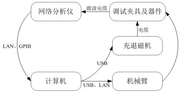
[0042] (1) Build a control system for debugging the device to be debugged. The device to be debugged is a lumped parameter surface mount circulator. The control system includes a computer, a network analyzer, a mechanical arm, a charging and demagnetizing machine, a debugging fixture, And three placement positions, in which the network analyzer, the manipulator and the charging and demagnetizing machine are all connected to the computer;

[0043] The network analyzer is used to obtain the S parameter data of the device to be debugged and send it to the computer;

[0044] The mechanical arm is used to move the device to be debugged according to the control of the computer;

[0045] The charging and demagnetizing machine is used to generate different charging and dema...

Embodiment 2

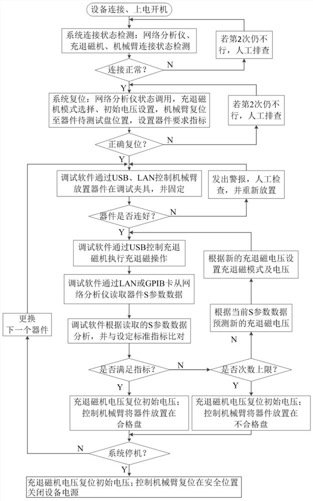
[0061] Example 2: see figure 1 , this embodiment is further improved on the basis of Embodiment 1. After the step (4) obtains the S parameter data of the initial state of the device to be debugged, it also includes: judging whether the device to be debugged is connected to the debugging fixture normally according to the S parameter data , if it is not normal, reinstall the device to be debugged after manual inspection, and reacquire the S parameter data of the initial state until the connection is normal.

[0062] It also includes step (7) judging whether the control system needs to be shut down;

[0063] If shutdown is required, the charging and demagnetizing machine is reset to the initial voltage, the mechanical arm is controlled to a safe position, and the power is turned off;

[0064] If the system does not need to be shut down, repeat steps (4)-(6) to debug the next device to be debugged.

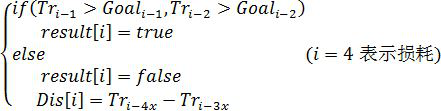
[0065] In the present invention, for the judgment of whether the performance in...


PUM


Abstract

The invention discloses an automatic rapid magnetic field debugging method suitable for lumped parameter surface-mounted circulator. The method comprises the steps: (1) constructing a control system used for debugging a device to be debugged, wherein the control system comprises a computer, a network analyzer connected with the computer, a mechanical arm, a magnetizing and demagnetizing machine, adebugging clamp and three placing positions, the placing positions corresponding to a device disc to be debugged, a qualified device disc and an unqualified device disc respectively; (2) starting thecontrol system for detection; (3) resetting the control system, and setting the magnetizing and demagnetizing machine to be in a demagnetizing mode, and making the mechanical arm reset to the position of the device disc to be debugged; (4) controlling the mechanical arm to take out a to-be-debugged device, installing the to-be-debugged device on the debugging clamp, and obtaining S parameter dataof the to-be-debugged device through the network analyzer; (5) controlling the magnetizing and demagnetizing machine to automatically adjust the voltage to adjust the magnetic field of the product; (6) judging whether the product is qualified or not; (7) carrying out sorting. Automatic debugging of the magnetic field of the device can be realized, the efficiency is greatly improved, and the production is more efficient and stable.

Description

technical field [0001] The invention relates to a debugging method, in particular to an automatic and fast debugging method suitable for the magnetic field of a surface-mounted circulator with lumped parameters. Background technique [0002] Microwave passive devices such as lumped parameter surface-mount circulators require magnetic field debugging to achieve the best performance. At present, the magnetic field debugging of the surface-mounted circulator with lumped parameters is basically carried out by manual charging and demagnetization, which has a large workload and low efficiency. performance at its best. And the artificial magnetic field debugging has the following deficiencies: [0003] (1) Due to the need to repeatedly operate the charging and demagnetizing equipment, the workload is heavy, the operation is complicated, and the efficiency is low; [0004] (2) Due to human factors, different people have certain differences in the judgment of the final result, the...

Claims


Application Information

Patent Timeline
IPC IPC(8): H01P1/38H01P11/00
CPCH01P1/38H01P11/00
Inventor 周永川吴江刘有彬闫欢胡艺缤白雪
Owner 中国电子科技集团公司第九研究所
Why Eureka
Try Eureka