
Installation method of tunnel cable and tunnel

An installation method, tunnel cable technology, applied in the direction of electrical components, wireless communication, network planning, etc., can solve problems such as communication quality conflicts at the installation location of leaking cables

Active Publication Date: 2020-10-23
CHINA UNITED NETWORK COMM GRP CO LTD
View PDF3 Cites 0 Cited by
  • Summary
  • Abstract
  • Description
  • Claims
  • Application Information

AI Technical Summary

Problems solved by technology

[0005] Embodiments of the present invention provide a tunnel cable installation method and a tunnel to solve the technical problem of conflict between the installation position of the newly added leaky cable and the guarantee of communication quality

Method used


Image

  • Installation method of tunnel cable and tunnel
  • Installation method of tunnel cable and tunnel
  • Installation method of tunnel cable and tunnel

Examples


Embodiment 1

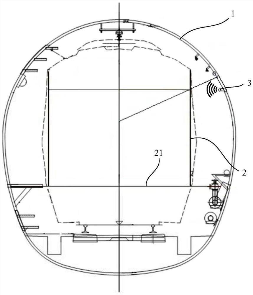
[0035] figure 2 The radiation schematic diagram of the tunnel cable provided by the embodiment of the present invention. This embodiment provides a method for installing tunnel cables, such as figure 2 As shown, including: installing the leakage cable 3 on the inner wall of the tunnel 1, the leakage cable 3 extends along the direction of the tunnel 1; the leakage cable 3 is higher than the upper edge of the window of the tunnel vehicle 2, or the leakage cable 3 and the tunnel vehicle 2 The upper edge of the window is flush; the slot 31 of the leakage cable 3 faces the direction of the window, and the leakage cable 3 is configured such that the radio frequency signal emitted from the slot 31 is injected into the compartment of the tunnel vehicle 2 through the window.

[0036] Here, the tunnel 1 should be understood in a broad sense, that is, the tunnel 1 may be a tunnel through which a train passes, a tunnel 1 through which a subway passes, or a road tunnel, which is not lim...

Embodiment 2

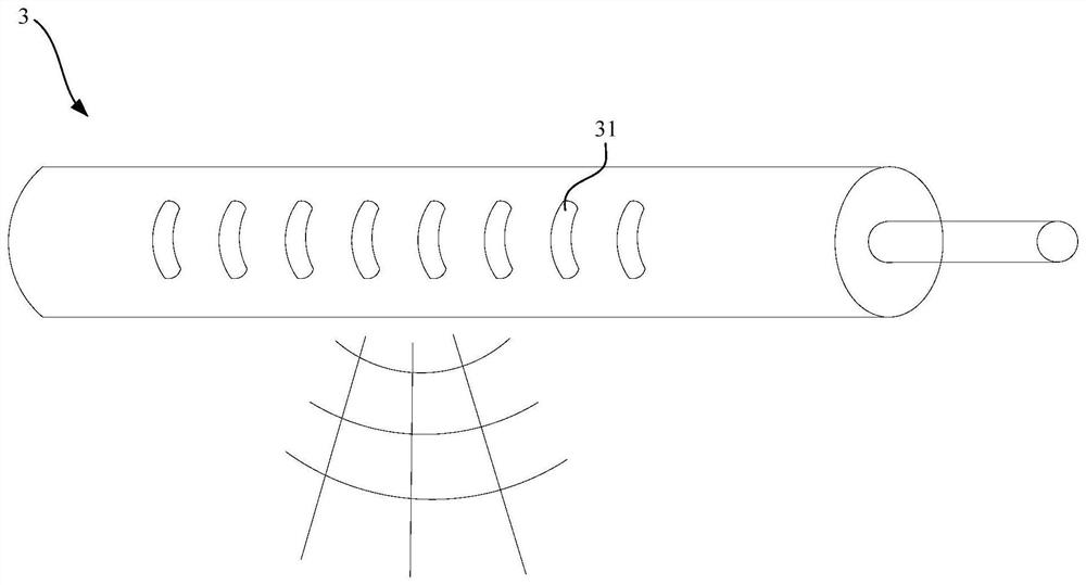
[0063] to combine figure 1 and figure 2, the present embodiment provides a tunnel 1, the tunnel 1 includes a track area and a tunnel wall surrounding the track area, the tunnel wall is provided with a leakage cable, the height of the leak cable from the track in the track area is not less than a first height, the first The height is the distance from the upper edge of the window of the tunnel vehicle 2 carried on the track to the height of the track; the leakage cable is provided with at least one slot 31, the opening of the slot 31 faces the direction of the window, and the radio frequency signal emitted from the slot 31 can The interior of the tunnel vehicle 2 is shot through the windows.

[0064] In this embodiment, the newly added leaky cable 3 may be used to transmit 5G network signals, so that passengers in the vehicle 2 driving in the tunnel 1 can connect to the 5G network.

[0065] In this embodiment, the slot 31 on the leakage cable 3 is not limited, and the slot 3...


PUM


Abstract

The invention relates to the technical field of wireless network transmission, in particular to an installation method of a tunnel cable and a tunnel, and aims to solve the problem of conflict betweenthe installation position of a newly added leakage cable and the guarantee of communication quality. According to the installation method of the tunnel cable, the installation method comprises the steps that a leakage cable is installed on a tunnel wall; the leakage cable is higher than or flush with the upper edge of a window of the tunnel vehicle; and the slotted hole of the leakage cable facesthe direction of the vehicle window, and the leakage cable is configured to emit a radio frequency signal from the slotted hole into the interior of the compartment of the vehicle through the vehiclewindow. Through the above arrangement, the newly added leakage cable used for transmitting the 5G network signal does not need to be installed on the tunnel wall directly facing the vehicle window, so that even if the area, directly facing the vehicle window, of the tunnel wall does not have enough space, the newly added leakage cable can also be installed in the tunnel to enable the 5G network signal to cover the tunnel; and meanwhile, the penetration loss of the vehicle to the signal is low, and the communication quality is high.

Description

technical field [0001] The invention relates to the technical field of wireless network transmission, in particular to a tunnel cable installation method and a tunnel. Background technique [0002] With the rapid evolution of communication network technology, the communication frequency is gradually developing towards high frequency bands, and 5G has emerged as the times require. Among them, the subway, as an important means of urban transportation, has a high density of people, which is a high-incidence scenario for 5G communication services. Due to the narrow space of subway tunnels, wireless signals are prone to fading during transmission in tunnels. Therefore, in order to ensure the quality of wireless communication in subways, leaky cables are usually used instead of antennas to send and receive signals. And because the frequency band of the 5G network is higher than the cut-off frequency of the leaky cable of the communication system that has been put into use in the ...

Claims


Application Information

Patent Timeline
IPC IPC(8): H04W16/18
CPCH04W16/18
Inventor 何明林铁力黄新波彭祷项崴叶勇
Owner CHINA UNITED NETWORK COMM GRP CO LTD
Learn More