System to increase the in-line power factor of a three-phase brushless DC motor

A power factor and power supply terminal technology, applied in the field of control systems, can solve the problems of power factor reduction and increase, and achieve the effect of low switching loss and low penetration loss

Active Publication Date: 2016-03-02
EBM PAPST MULFINGEN GMBH & CO KG
View PDF7 Cites 0 Cited by
  • Summary
  • Abstract
  • Description
  • Claims
  • Application Information

AI Technical Summary

Problems solved by technology

It is known that according to the mathematical relationship, the power factor is related to the distortion coefficient THD (Total Harmonic Distortion, Total Harmonic Distortion) and the phase difference φ of the main wave, where the increase of the distortion coefficient THD leads to the reduction of the power factor

Method used


Image

  • System to increase the in-line power factor of a three-phase brushless DC motor
  • System to increase the in-line power factor of a three-phase brushless DC motor
  • System to increase the in-line power factor of a three-phase brushless DC motor

Examples


Embodiment Construction

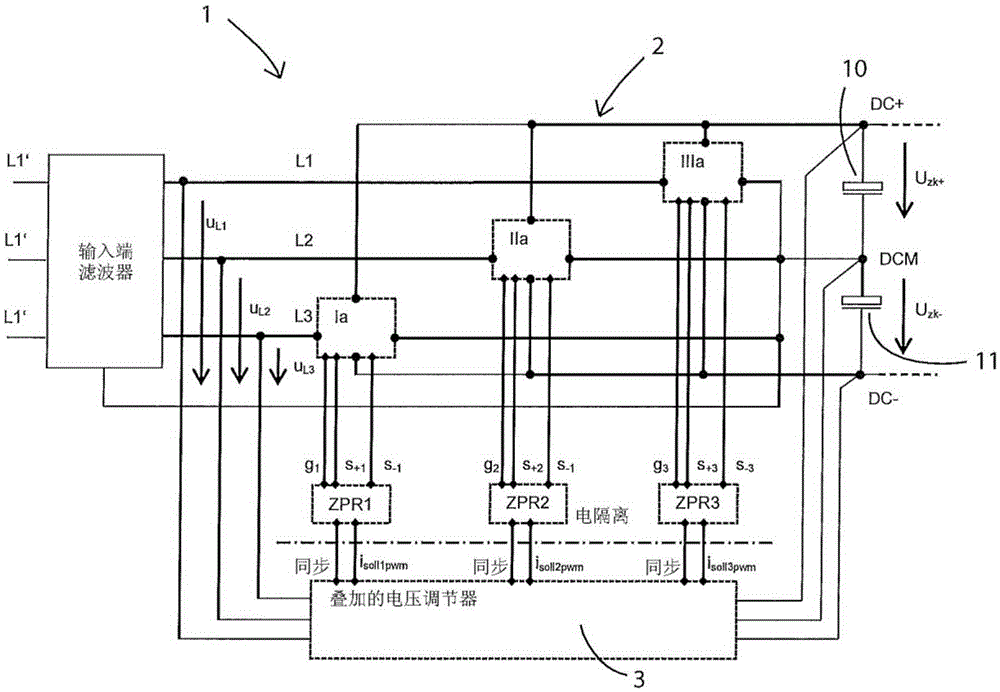
[0033] exist figure 1 An embodiment of a circuit structure with cascade regulation according to the present invention is shown in . It shows a control system 1 for increasing the supply-side power factor λ of a three-phase powered EC motor with a direct voltage intermediate circuit 2 for generating the intermediate circuit positive potential DC+ and negative DC potential and The potential at the intermediate circuit middle section DCM lies between them. The positive intermediate circuit potential DC+ represents the potential at the upper contact of the intermediate circuit capacitor 10 , while the negative intermediate circuit potential DC− represents the potential at the lower contact of the intermediate circuit capacitor 11 . The intermediate circuit voltage share Uzk+ represents the potential difference between the potentials DC+ and DCM, and the intermediate circuit voltage share Uzk− represents the potential difference between the potentials DCM and DC−. The intermediat...


PUM


Abstract

The present invention relates to a control system and a method for raising the mains-side power factor A of three-phase fed EC motors having a dc voltage intermediate circuit (2) with an intermediate center tap (DCM) for generating a positive and a negative intermediate circuit potential (DC+, DC-), comprising three active bridge arms (Ia, IIa, IIIa), each of which are connected to a subordinate two-point current control (ZPR1, ZPR2, ZPR3) and, in each case, via said current control to a superimposed intermediate circuit voltage control (3), which controls the potential difference between the middle circuit potentials (DC+, DC-) via set point settings for the subordinate two-point current controllers (ZPR1, ZPR2, ZPR3).

Description

technical field [0001] The present invention relates to a control system for increasing the power factor λ at the power supply end of a three-phase powered EC motor according to the feature of technical solution 1, and a control system using this control system according to the feature of technical solution 12 method. Background technique [0002] EC motors (EC=electronic commutation) are well known and used for a wide range of applications. EC motors are known as permanent-magnet-excited, slip-ring-free synchronous motors, which are usually provided with a rotor position sensor and are operated with DC voltage via commutation electronics (control and power electronics). The direct voltage can be obtained, for example, as an intermediate circuit direct voltage by rectification of the mains alternating voltage. From this direct voltage, the commutation electronics generate, depending on the rotor position, an in particular three-phase alternating voltage for forming a rotat...

Claims


Application Information

Patent Timeline
IPC IPC(8): H02M1/42H02M1/00
CPCH02M7/00H02P6/28H02M1/4216Y02B70/10Y02P80/10H02M1/0009H02P6/14
Inventor F·施耐德
Owner EBM PAPST MULFINGEN GMBH & CO KG
Why Eureka
Try Eureka