
Underground diaphragm wall prefabricating method for built-in capillary tube heat exchanger

An underground diaphragm wall and capillary tube technology, applied in geothermal collectors, sheet pile walls, geothermal energy, etc., can solve the problems of inability to apply geothermal energy, floor space, and initial investment impact

Inactive Publication Date: 2020-10-27
QINGDAO TECHNOLOGICAL UNIVERSITY
View PDF0 Cites 1 Cited by
  • Summary
  • Abstract
  • Description
  • Claims
  • Application Information

AI Technical Summary

Problems solved by technology

Affected by the area occupied by buried pipes and the initial investment, traditional soil source heat pump systems are difficult to apply in densely built urban areas. Therefore, it is impossible to apply clean and renewable geothermal energy in urban energy-intensive areas.

Method used


Image

  • Underground diaphragm wall prefabricating method for built-in capillary tube heat exchanger
  • Underground diaphragm wall prefabricating method for built-in capillary tube heat exchanger
  • Underground diaphragm wall prefabricating method for built-in capillary tube heat exchanger

Examples


Embodiment 1

[0062] Embodiment 1 of the present disclosure provides a prefabrication process of an outer underground diaphragm wall with a built-in capillary heat exchanger, and the steps are as follows:

[0063] A prefabrication process of an underground diaphragm wall with a built-in capillary heat exchanger, including the construction of the underground diaphragm wall guide wall, drilling rig drilling, drilling and grasping machine to form grooves, pouring high-quality mud to protect the wall, inspecting the capillary, braiding the steel bar structure, fixing the capillary, and inserting the steel bar Structural, concrete pouring, capillary row connections, pressure testing, incorporating diaphragm walls.

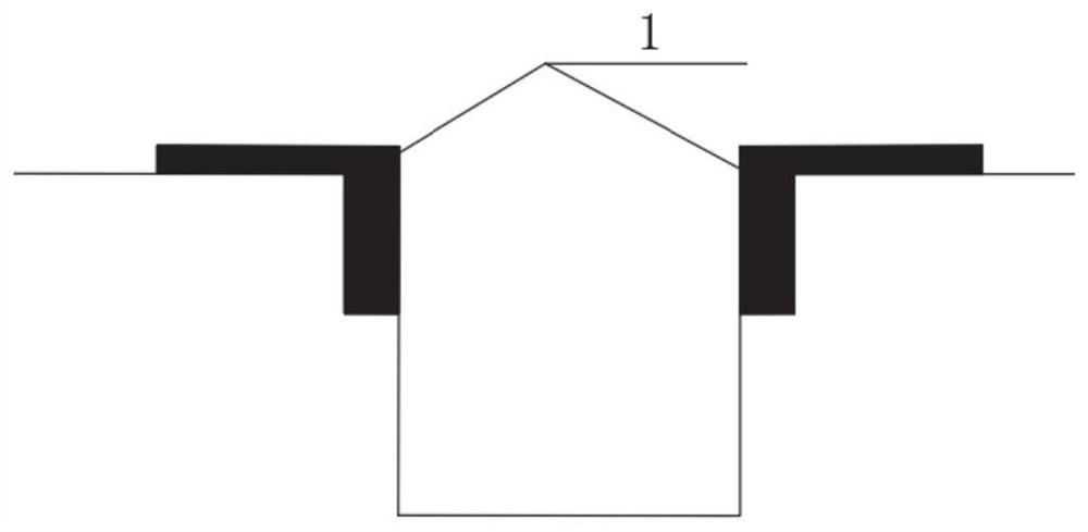
[0064] 1. Construction of underground diaphragm wall guide wall

[0065] like figure 1 As shown, the construction of the underground diaphragm wall guide wall 1 is to determine the construction scope of the subway station, reduce construction errors and lay a good foundation for the...

Embodiment 2

[0089] Embodiment 2 of the present disclosure provides a prefabrication process of an inner underground diaphragm wall with a built-in capillary heat exchanger. This embodiment is the case of two-layer continuous wall.

[0090] In the construction of some subway stations, the subway station directly uses the underground diaphragm wall as the enclosure structure. However, considering the water permeability of the underground diaphragm wall, some subway stations in recent years will directly build a waterproof structure on the outside or in the underground diaphragm wall when they are built. Build a layer of inner wall 12 as a supporting structure inside the inner side, and this layer of supporting structure is also called an underground diaphragm wall. Due to the use of space-time effects, the inner underground diaphragm wall can be constructed horizontally and extended vertically. This layer of underground diaphragm wall is connected with the outer layer of underground diaphra...

Embodiment 3

[0100] Embodiment 3 of the present disclosure provides an underground continuous wall prefabrication process with built-in capillary heat exchangers between walls.

[0101] like Figure 8 As shown, for embodiments 1 and 2, considering that the two-layer diaphragm wall 10, 12 may be equipped with two layers of capillary tubes will be redundant and inconvenient for construction, it may be considered to place the capillary tube in the middle of the two-layer diaphragm wall 10, 12. This built-in method can be independent of steel and concrete.

[0102] Concrete construction method and embodiment 1 and embodiment 2 different operations are: treat that the capillary row is bonded on the outer diaphragm wall 10 with adhesive after the foundation pit bottom layer construction is finished, and spray on the outer diaphragm wall 10 with cement mortar, thickness Just cover the capillary, and then follow the normal construction process of the subway station.


PUM


Abstract

The invention relates to an underground diaphragm wall prefabricating method for a built-in capillary tube heat exchanger. The underground diaphragm wall prefabricating method comprises the followingsteps of: in each segment of diaphragm wall, independently constructing diaphragm wall guide walls, drilling on a position near the diaphragm wall between two diaphragm wall guide walls, and graspinga groove between the two diaphragm wall guide walls; fixing a capillary tube and a reinforcement cage, checking the air tightness of capillary tube branch tubes, sealing two ends by a plurality of capillary tube branch tubes in the presence of air, fixing capillary tube main tubes with the reinforcement cage, connecting the plurality of capillary tube branch tubes with a plurality of capillary tube main tubes, placing an integral structure of the reinforcement cage and the plurality of capillary tube branch tubes in the groove along external diaphragm wall guide walls, and pouring concrete into the groove to fix the reinforcement cage; connecting the capillary tube main tubes, and connecting the capillary tube main tubes with a water collection manifold (water knockout drum) branch tubes;and arranging a crown beam above a reinforcement structure, pouring the concrete to enable the concrete to cover the crown beam and the capillary tube main tubes, and forming a plurality of diaphragmwalls into a whole. According to the underground diaphragm wall prefabricating method, quick construction of the underground diaphragm wall of the built-in capillary tube heat exchanger is realized.

Description

technical field [0001] The invention belongs to the technical field of underground construction, in particular to a method for prefabricating an underground continuous wall with a built-in capillary heat exchanger. Background technique [0002] The information disclosed in this Background section is only for enhancement of understanding of the general background of the invention and should not necessarily be taken as an acknowledgement or any form of suggestion that this information forms the prior art already known to a person of ordinary skill in the art. [0003] The soil source heat pump system is a device that uses the relatively stable temperature of the soil at room temperature underground to complete heat exchange with the interior of the building through the pipeline system buried around the building. The buried pipe of the soil source heat pump system occupies a large area, especially the horizontal buried pipe, which has a relatively large area. Affected by the a...

Claims


Application Information

Patent Timeline
Patent Type & Authority Applications(China)
IPC IPC(8): E02D5/18F24T10/13
CPCE02D5/18E02D2250/0023F24T10/13Y02E10/10
Inventor 季永明胡松涛吴汶泽刘国丹佟振童力
Owner QINGDAO TECHNOLOGICAL UNIVERSITY
Learn More