System and method for eliminating crystals of selective catalytic reduction system

A selective and crystallization technology, applied in the control equipment for eliminating the crystallization of the selective catalytic reduction system, eliminating the crystallization of the selective catalytic reduction system, and the field of computer-readable storage media, can solve the problems such as crystallization monitoring cannot be realized

Active Publication Date: 2020-10-27
BEIJING FOTON CUMMINS ENGINE
View PDF5 Cites 3 Cited by
  • Summary
  • Abstract
  • Description
  • Claims
  • Application Information

AI Technical Summary

Problems solved by technology

[0005] The purpose of the embodiments of the present invention is to provide a system and method for eliminating crystallization in the selective catalytic reduction system. The system and method aim to solve the crystallization failure problem of the SCR after-treatment system in the prior art when the urea injection is not stopped. Inspection, failure to realize crystallization monitoring, and technical problems such as multiple OBD alarms caused by untimely crystallization failures and oil dilution caused by multiple trigger regenerations

Method used


Image

  • System and method for eliminating crystals of selective catalytic reduction system
  • System and method for eliminating crystals of selective catalytic reduction system

Examples


Embodiment 1

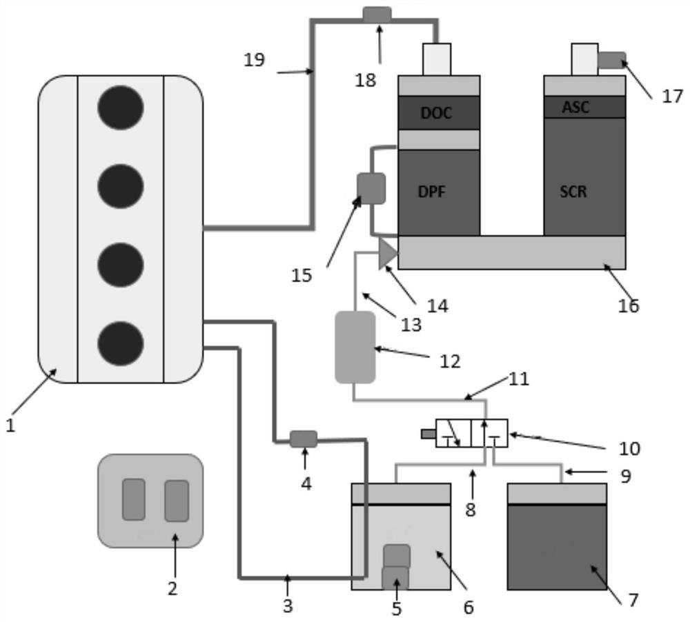
[0084] A system for eliminating engine SCR post-treatment crystallization, including engine 1, ECM 2, coolant pipeline 3, electromagnetic switch 4, temperature-liquid level sensor 5, water tank 6 (the liquid is water), urea tank 7 (the Said solution is urea), water suction pipe 8 (the second suction pipe), liquid suction pipe 9 (the first suction pipe), two-position three-way solenoid valve 10, liquid transmission pipe 11 (the transmission pipe ), urea pump 12 (the pump), injection line 13, nozzle 14 (the injection device includes injection line and nozzle), DPF differential pressure and pressure sensor 15, SCR aftertreatment 16 (the selective catalytic reduction system) , outlet NOX sensor 17, inlet NOX sensor 18 and exhaust tailpipe 19.

[0085] Wherein, the inlet NOX sensor 18 is installed on the exhaust tailpipe 19 for measuring the original NOX of the engine, one end of the exhaust tailpipe 19 is connected to the engine 1, and the other end is connected to the SCR post-pr...

Embodiment 2

[0096] Based on Embodiment 1, under the normal working mode (the normal working state), the urea solution in the urea tank 7 passes through the suction pipe 9, the two-position three-way solenoid valve 10, the liquid transfer pipe 11, and the urea solution under the control of the ECM2. The pump 12, injection line 13, and nozzle 14 enter the SCR post-treatment 16 to react with NOX;

[0097] Wherein, when there is crystallization in the SCR post-processing 16 detected by the DPF differential pressure and pressure sensor 15, the outlet NOX sensor 17, and the inlet NOX sensor 18, switch to the temporary working state, the nozzle 14 is opened, and the ECM2 controls the urea pump 12 to execute Reverse, the remaining urea in the nozzle 14 returns to the urea tank 7 through the injection line 13, the urea pump 12, the liquid transfer pipe 11, the two-position three-way solenoid valve 10, and the suction pipe 9, that is, the residual urea back-absorption process, NOX-related OBD diagn...


PUM


Abstract

The invention provides a method for eliminating the crystals of a selective catalytic reduction system, and belongs to the technical fields of engines and tail gas treatment. The method comprises thefollowing steps: monitoring the crystals in the selective catalytic reduction system in a normal working state; while monitoring the crystals in the selective catalytic reduction system, switching over the normal working state to a temporary working state; and executing elimination operation corresponding to the crystals in the temporary working state. The method is capable of monitoring the crystals in the SCR aftertreatment system; according to the method, the crystals in the SCR aftertreatment system are treated, the OBD alarming times caused by high NOX emission are reduced, and the timesof regeneration for activating SCR performance are reduced, so that engine oil dilution caused by multiple regenerations is prevented; and the method has the advantages of being simple in structure, low in cost, and good in use effect.

Description

technical field [0001] The invention relates to the technical field of engine and exhaust gas treatment, in particular to a method for eliminating crystallization in a selective catalytic reduction system, a control system for eliminating crystallization in a selective catalytic reduction system, and a monitoring system for eliminating crystallization in a selective catalytic reduction system , A control device for eliminating crystallization in a selective catalytic reduction system, and a computer readable storage medium. Background technique [0002] With the upgrading of emission regulations, the SCR (Selective Catalyst Reduction) after-treatment system is widely used in diesel engines, which can effectively reduce nitrogen oxides (NOX) in exhaust gas, but in actual use, urea crystallization problem Prominent, which in turn leads to the on-board diagnostic system (On Board Diagnostics, OBD) alarm, frequent regeneration, and oil dilution problems. [0003] Application CN...

Claims


Application Information

Patent Timeline
Patent Type & Authority Applications(China)
IPC IPC(8): F01N3/20F01N11/00F01N9/00
CPCF01N3/208F01N9/002F01N11/00F01N11/002F01N2570/14F01N2610/02F01N2610/1486Y02T10/12Y02T10/40
Inventor 薛俊强杜鑫郝庆栋
Owner BEIJING FOTON CUMMINS ENGINE
Why Eureka
Try Eureka