Heat exchange pipe capable of achieving stable heat exchange based on magnetic self-driving

A self-driven, heat exchange tube technology, applied in the field of heat exchange tubes, can solve the problems of inability to increase the fluidity of the external heat dissipation medium on the external tube wall, low heat exchange efficiency between media, and high cost of medium consumption.

Active Publication Date: 2020-10-27
南海龙
View PDF7 Cites 0 Cited by
  • Summary
  • Abstract
  • Description
  • Claims
  • Application Information

AI Technical Summary

Problems solved by technology

[0007] Aiming at the deficiencies of the existing technology, the present invention provides a heat exchange tube based on magnetic self-drive to realize stable heat exchange, which solves the problem that the traditional heat exchange tube ca

Method used


Image

  • Heat exchange pipe capable of achieving stable heat exchange based on magnetic self-driving
  • Heat exchange pipe capable of achieving stable heat exchange based on magnetic self-driving
  • Heat exchange pipe capable of achieving stable heat exchange based on magnetic self-driving

Examples


Embodiment 1

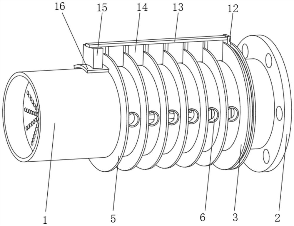
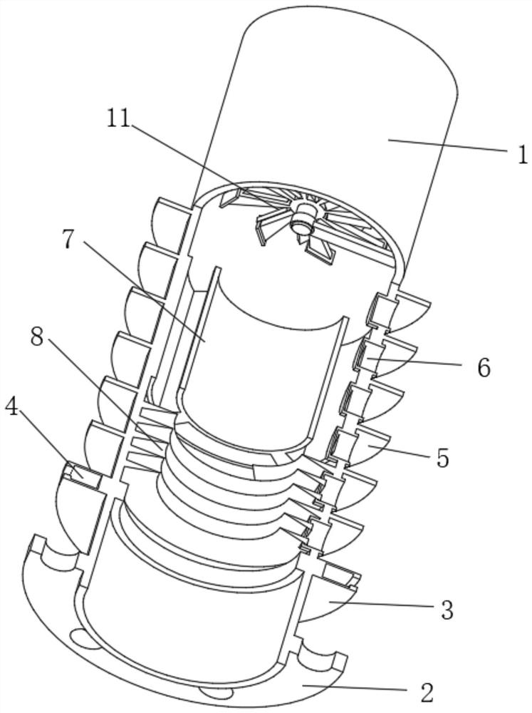
[0036] Such as Figure 1-3 As shown, the present invention provides a technical solution: a heat exchange tube that realizes stable heat exchange based on magnetic self-driving, including a heat exchange inner tube 1, and the output end of the heat exchange inner tube 1 is fixedly connected with a mounting flange 2 , the position of the heat exchange inner tube 1 close to the output end is fixedly connected with the outer limit fin 3, the inside of the outer limit fin 3 extends to the inside of the heat exchange inner tube 1, and the inside of the outer limit fin 3 is located in the heat exchange inner tube The outer position of the tube 1 is provided with a limiting track 4, the outer surface of the heat exchange inner tube 1 and the position at the input end of the outer limiting fin 3 are uniformly and fixedly connected with the heat exchange outer fin 5, and the outer front of the heat exchange inner tube 1 is The position between the heat exchange outer fins 5 is evenly f...

Embodiment 2

[0039] Such as Figure 1-3 As shown, on the basis of Embodiment 1, the present invention provides a technical solution: a heat exchange tube that realizes stable heat exchange based on magnetic self-drive, and the inner sliding connection of the limiting track 4 is connected with a transmission slider 12, and the transmission slider The outer end of 12 is fixedly connected with an outer transmission strut 13, and the bottom surface of the outer transmission strut 13 is uniformly and fixedly connected with a driving stirring piece 14, and the position between the driving stirring piece 14 and the heat exchange outer fin 5 is correspondingly arranged.

[0040] The bottom of the outer transmission strut 13 close to the input end is fixedly connected with a transmission auxiliary block 15, and the bottom of the transmission auxiliary block 15 is fixedly connected with an arc-shaped magnetic block 16, and the arc-shaped magnetic block 16 is correspondingly arranged with the fan driv...

Embodiment 3

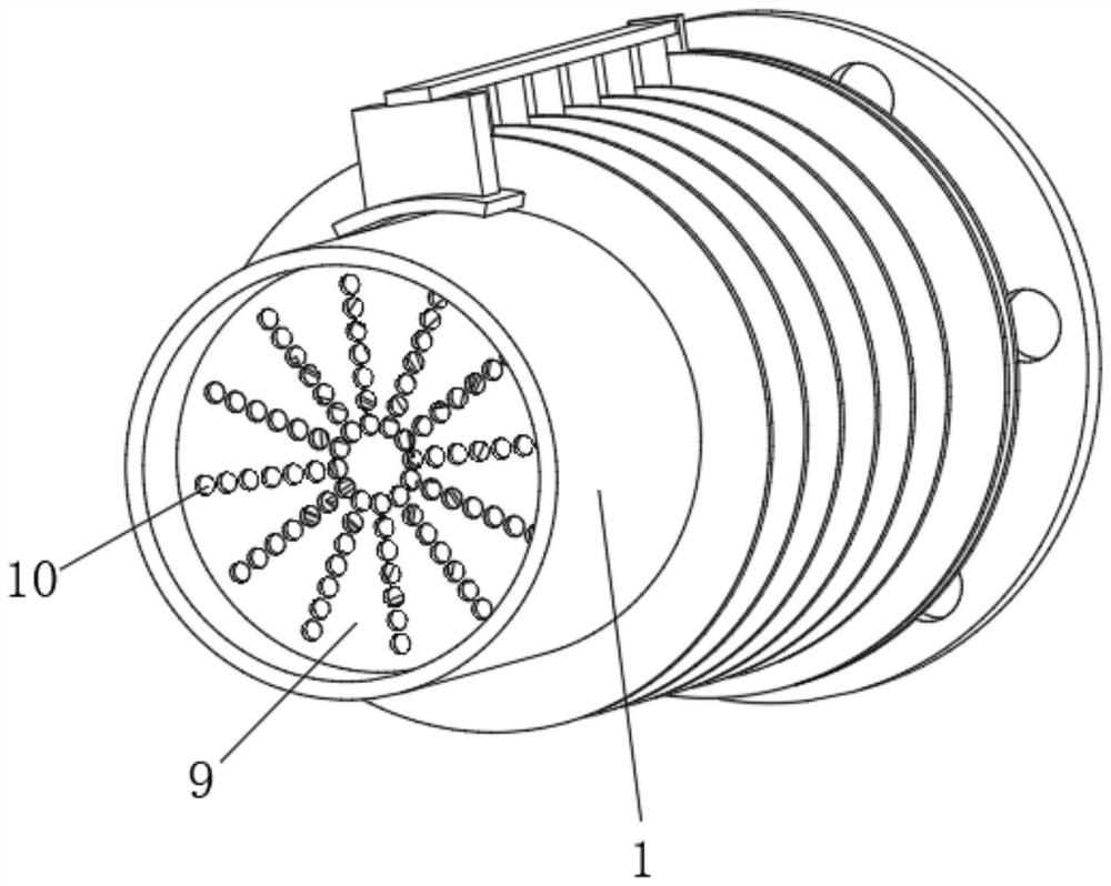
[0042] Such as Figure 4 As shown, on the basis of Embodiment 1 and Embodiment 2, the present invention provides a technical solution: a heat exchange tube based on magnetic self-driving to achieve stable heat exchange, and the dispersed heat exchange mechanism 7 includes an inner heat exchange fin 701, The outer side of the inner heat exchange fin 701 is fixedly connected with the heat exchange inner pipe 1, the inner heat exchange slot 702 is provided at the middle position of the inner heat exchange fin 701, and the outer heat exchange slot 703 is evenly opened on the outer side of the inner heat exchange fin 701 . The heat exchange of the heat exchange medium is achieved in different regions, and the local rapid heat exchange of the heat exchange medium is realized.

[0043] One end of the heat exchange groove 6 located inside the heat exchange inner tube 1 is arranged corresponding to the inside of the outer heat exchange tank 703 .


PUM


Abstract

The invention discloses a heat exchange pipe capable of realizing stable heat exchange based on magnetic self-driving, and relates to the technical field of heat exchange pipes. The heat exchange pipecomprises a heat exchange inner through pipe. Heat exchange outer fins are fixedly connected to the surface of the exterior of the heat exchange inner through pipe and located at the input end of anouter limiting fin. Heat exchange grooves are fixedly connected to the front surface of the outer portion of the heat exchange inner through pipe and located between the heat exchange outer fins. Theposition, close to the input end, of the inner surface of the heat exchange inner through pipe is fixedly connected with a dispersion heat exchange mechanism. The position, located at the output end of the dispersion heat exchange mechanism, of the interior of the heat exchange inner through pipe is fixedly connected with a spiral inner heat exchange sheet. The position, located at the input end of the dispersion heat exchange mechanism, of the interior of the heat exchange inner through pipe is fixedly connected with a fan blade driving mechanism. The heat exchange pipe capable of achieving stable heat exchange based on magnetic self-driving achieves the purposes of prolonging the staying time of a heat exchange medium, ensuring that heat is sufficiently absorbed by the heat exchange medium, and increasing the heat exchange utilization rate of the heat exchange medium per unit volume.

Description

technical field [0001] The invention relates to the technical field of heat exchange tubes, in particular to a heat exchange tube that realizes stable heat exchange based on magnetic self-driving. Background technique [0002] The heat exchange tube is one of the elements of the heat exchanger, which is placed inside the cylinder and used for the exchange of heat between the two media. Has high thermal conductivity and good isothermal properties. It is a device that transfers thermal energy from one point to another quickly and with almost no heat loss, so it is called a heat transfer superconductor, and its thermal conductivity is thousands of times that of copper. [0003] For example, the Chinese Invention Publication No. is: CN109798787A, a heat exchange tube comprising an outer tube made of aluminum, an intermediate tube and an inner tube made of copper, and the intermediate tube is sleeved on the inner tube, and the The outer tube is sleeved on the middle tube, and t...

Claims


Application Information

Patent Timeline
IPC IPC(8): F28F1/42F28F13/00F28F13/12F28F9/12F28F9/22F28F19/01F28G3/10
CPCF28F1/42F28F13/00F28F13/125F28F9/12F28F9/22F28F19/01F28G3/10
Inventor 南海龙
Owner 南海龙
Why Eureka
Try Eureka