An overflow structure of a water bath vaporizer

A water-bath vaporizer and overflow technology, which is applied to pressure vessels, vessel discharge methods, and equipment discharged from pressure vessels, etc., can solve the problem of unbalanced distribution of water temperature areas in the lower part of the tank, increasing the difficulty of design and assembly, and poor maintenance. Convenience and other problems, to achieve the effect of uniform distribution of water temperature and temperature zone, convenient assembly and maintenance, and stable heat exchange process

Active Publication Date: 2018-08-03
CHINA NAT AIR SEPARATION ENG CO LTD
View PDF9 Cites 1 Cited by
  • Summary
  • Abstract
  • Description
  • Claims
  • Application Information

AI Technical Summary

Problems solved by technology

[0006] 1. The overflow pipe is located inside the tank, and the internal space of the bubbling vaporizer is large, so it can be installed in this way, but the internal space of the water-bath vaporizer will be relatively compact, and the overflow pipe located inside will increase the difficulty of design and assembly, and subsequent maintenance will not be easy. Convenient; and the overflow pipe is located in the liquid, and the overflow liquid in the pipe will exchange heat with the liquid outside the pipe during the rising process, which will still cause heat loss
[0007] 2. The bottom of the overflow pipe only absorbs water at a certain position in the lower part of the tank, which will cause unbalanced distribution of the water temperature area in the lower part of the tank

Method used


Image

  • An overflow structure of a water bath vaporizer
  • An overflow structure of a water bath vaporizer
  • An overflow structure of a water bath vaporizer

Examples


Embodiment Construction

[0023] The present invention will be further described in detail below in conjunction with the accompanying drawings and examples. The following examples are explanations of the present invention and the present invention is not limited to the following examples.

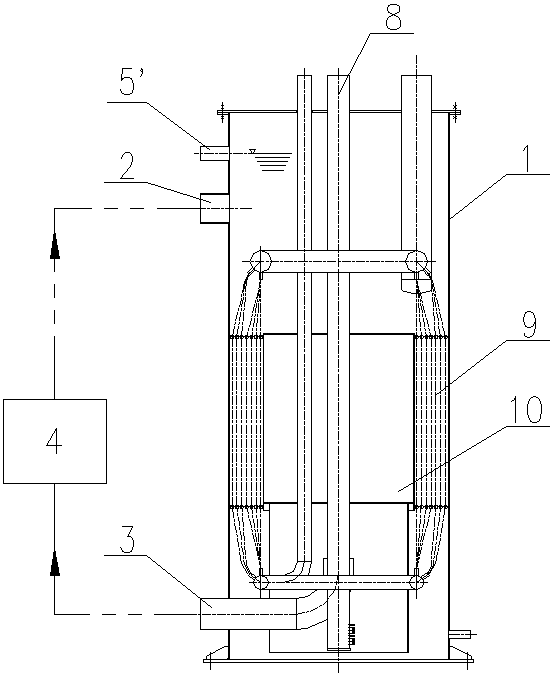
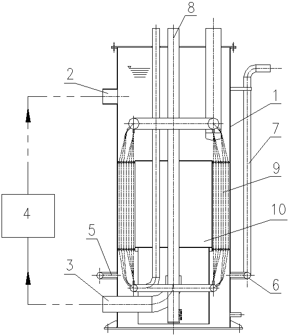
[0024] see Figure 1 ~ Figure 4 In the embodiment of the present invention, a water inlet 2 is provided on the upper part of the water storage cylinder 1, a water outlet 3 is provided on the lower part, and a circulating water pump 4 is provided between the water outlet 3 and the water inlet 2. The medium water in the lower part of the water storage cylinder 1 and inside the central tube 10 of the tube bundle is heated by the steam injection pipe 8 and then introduced into the circulating water pump 4 through the water pump 3 for pressurization, and enters the upper part of the water storage cylinder 1 through the water inlet 2 .

[0025] The water storage cylinder 1 is provided with a water storage chamber for stor...


PUM


Abstract

The invention relates to an overflow structure of a water bath vaporizer and overcomes the heat loss caused by direct discharge of a large amount of hot water which is not subjected to heat exchange, so that the consumption of water vapor is further reduced and the heat transfer efficiency is improved. A water storage barrel is internally provided with a water storage chamber for storing liquid water; overflow openings are formed in the water storage barrel; a water inlet is formed in the upper part of the water storage barrel while a water suction opening is formed in the lower part of the water storage barrel; the overflow openings are formed in the lower part of the water storage barrel and positioned above the water suction opening and are communicated with the lower part of the water storage chamber; the plurality of overflow openings are horizontally and uniformly distributed in the peripheral direction of the water storage barrel; a liquid collecting pipe is circular, is horizontally positioned at the periphery of the water storage barrel and is fixed together and communicated with the overflow openings; an ascension pipe is vertically arranged, the bottom end of the ascension pipe is fixed together and communicated with the liquid collecting pipe, the top end of the ascension pipe is communicated with atmosphere, and when the top end is higher than the liquid level of liquid water in the water storage barrel, the ascension pipe is bended in the horizontal direction; the bended pipe body is horizontally arranged, and a small hole is formed in the top of the pipe body.

Description

technical field [0001] The invention relates to an overflow structure of a water-bath vaporizer. Background technique [0002] see figure 1 , the working principle of the water bath vaporizer is to use water vapor as a heat source, the water storage tank 1 is provided with a water storage cavity for storing liquid water, the liquid water in the water storage tank 1 is used as an intermediate heat transfer medium, and the heating is located in the low temperature liquid winding tube bundle 9 The low-temperature liquid fluid inside is often used for the vaporization and transportation of low-temperature liquefied gases (such as liquid oxygen, liquid nitrogen, etc.). Usually, the circulating flow rate of the liquid water on the water side is enhanced by configuring the external circulating water pump 4, thereby increasing the convective heat release coefficient of the circulating hot water. The circulating flow direction of hot water in the water storage cylinder 1 is from to...

Claims


Application Information

Patent Timeline
Patent Type & Authority Patents(China)
IPC IPC(8): F17C7/04
Inventor 丁传琪张行东李燕鹏李万军
Owner CHINA NAT AIR SEPARATION ENG CO LTD
Why Eureka
Try Eureka