
Electronic device cooling device

A cooling device, electronic device technology, applied in the direction of electric solid devices, electrical components, semiconductor devices, etc., can solve the problems of system collapse, system reliability reduction, chip damage, etc., to achieve the effect of smooth liquid transportation

Active Publication Date: 2020-09-01
INST OF ENGINEERING THERMOPHYSICS - CHINESE ACAD OF SCI
View PDF7 Cites 1 Cited by
  • Summary
  • Abstract
  • Description
  • Claims
  • Application Information

AI Technical Summary

Problems solved by technology

The control of chip temperature is very important. For electronic chips that work stably and continuously, the maximum temperature cannot exceed 85°C. If the temperature is too high, the chip will be damaged.
Studies have shown that in the range of 70-80 °C, the reliability of the system will decrease by 50% for every 10 °C increase in the temperature of a single electronic component
According to statistics, more than 55% of electronic equipment fails due to overheating
Therefore, in order to ensure the normal, stable and reliable operation of electronic equipment, the waste heat generated by power dissipation must be taken away in time, otherwise the local temperature of the chip will be too high, which will greatly reduce the working performance, stability and service life of the equipment, and even cause Chip thermal deformation and system crash, heat dissipation is the bottleneck problem restricting its development
At present, traditional cooling methods such as air cooling, forced water cooling, heat pipes, semiconductor refrigeration, and micro-channel cooling technologies have limited room for improvement in cooling capacity, and it is difficult to meet the actual heat dissipation needs of electronic equipment with increasing power density.

Method used


Image

  • Electronic device cooling device
  • Electronic device cooling device

Examples


Embodiment Construction

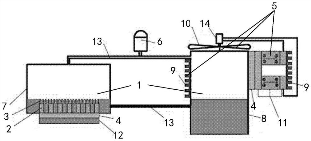
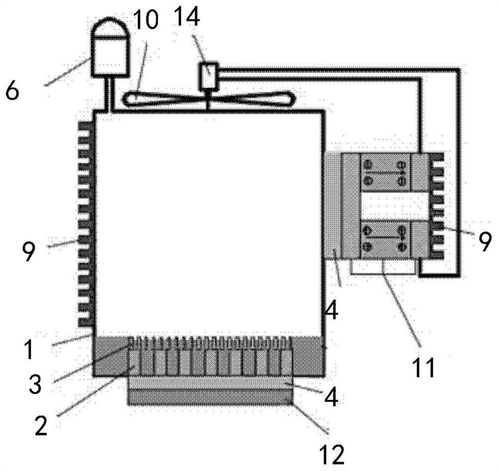
[0024] A cooling device for electronic devices, comprising a working body 1, a heat dissipation device 5 and an energy storage device 6, wherein: the working body 1, the working body 1 is a sealed cavity, a cooling medium is arranged in the sealed cavity, and a cooling medium is arranged on the inner bottom surface of the sealed cavity. A plurality of microchannels 2, the upper part of the microchannel 2 is provided with a nanoporous film 3 with capillary force, and the bottom surface of the sealed cavity is provided with a heat conduction structure 4, and the electronic device 12 exchanges heat with the cooling medium through the heat conduction structure 4; the heat dissipation device 5, It is arranged on the outer surface of the working body 1 to dissipate the heat in the working body 1; the energy storage device 6 is arranged on the upper part of the working body 1 to stabilize the pressure in the working body.

[0025] In order to make the object, technical solution and ad...


PUM

PropertyMeasurementUnit
Thicknessaaaaaaaaaa
Inner diameteraaaaaaaaaa

Abstract

The invention provides an electronic device cooling device. The device comprises a working body (1), wherein the working body (1) is a sealed cavity, a cooling medium is arranged in the sealed cavity,a plurality of micro-channels (2) are arranged on the inner bottom surface of the sealed cavity, nano porous films (3) with capillary force are arranged at the upper parts of the micro-channels (2),a heat conduction structure (4) is arranged outside the bottom surface of the sealed cavity, and an electronic device (12) exchanges heat with the cooling medium through the heat conduction structure(4); the heat dissipation device (5) is arranged on the outer surface of the working body (1) so as to dissipate heat in the working body (1); and the energy storage device (6) is arranged at the upper part of the working body (1) and is used for stabilizing the pressure in the working body.

Description

technical field [0001] The present disclosure relates to the technical field of thermal management of electronic equipment, in particular to an electronic device cooling device. Background technique [0002] With the rapid development of high performance, miniaturization and integration of electronic equipment, its power consumption per unit volume and heat flux have increased sharply. It is predicted that the average heat flux density of electronic chips will reach 500W / cm 2 , the local hot spot heat flux will exceed 1000W / cm 2 . The control of chip temperature is very important. For electronic chips that work stably and continuously, the maximum temperature cannot exceed 85°C. If the temperature is too high, the chip will be damaged. Studies have shown that in the range of 70-80 °C, the reliability of the system will decrease by 50% for every 10 °C increase in the temperature of a single electronic component. According to statistics, more than 55% of electronic devices...

Claims


Application Information

Patent Timeline
IPC IPC(8): H01L23/427H01L23/467
CPCH01L23/427H01L23/467Y02D10/00
Inventor 成克用淮秀兰
Owner INST OF ENGINEERING THERMOPHYSICS - CHINESE ACAD OF SCI
Learn More