
Calibration device for scanning system and calibration method of calibration device

A scanning system and calibration device technology, applied in the direction of using optical devices, measuring devices, instruments, etc., can solve problems such as strong subjectivity, large errors, and inability to achieve multiple calibrations.

Inactive Publication Date: 2020-10-27
HUNAN FARSOON HIGH TECH CO LTD
View PDF8 Cites 0 Cited by
  • Summary
  • Abstract
  • Description
  • Claims
  • Application Information

AI Technical Summary

Problems solved by technology

The calibration plate used in this method needs to go through a series of complex operations such as positioning and leveling before calibration, and it is only calibrated once before construction, which cannot achieve multiple calibrations during the construction process, and the information collected during the calibration process is often measured manually. , strong subjectivity, large error

Method used


Image

  • Calibration device for scanning system and calibration method of calibration device
  • Calibration device for scanning system and calibration method of calibration device
  • Calibration device for scanning system and calibration method of calibration device

Examples


Embodiment Construction

[0033] In order to facilitate the understanding of the present invention, the following will describe the present invention more fully and give preferred embodiments of the present invention. However, the present invention can be embodied in many different forms and is not limited to the embodiments described herein. On the contrary, these embodiments are provided to make the understanding of the disclosure of the present invention more thorough and comprehensive.

[0034] Unless otherwise defined, all technical and scientific terms used herein have the same meaning as commonly understood by one of ordinary skill in the technical field of the invention. The terms used herein in the description of the present invention are for the purpose of describing specific embodiments only, and are not intended to limit the present invention. As used herein, the term "and / or" includes any and all combinations of one or more of the associated listed items.

[0035] Such as figure 1 As sh...


PUM


Abstract

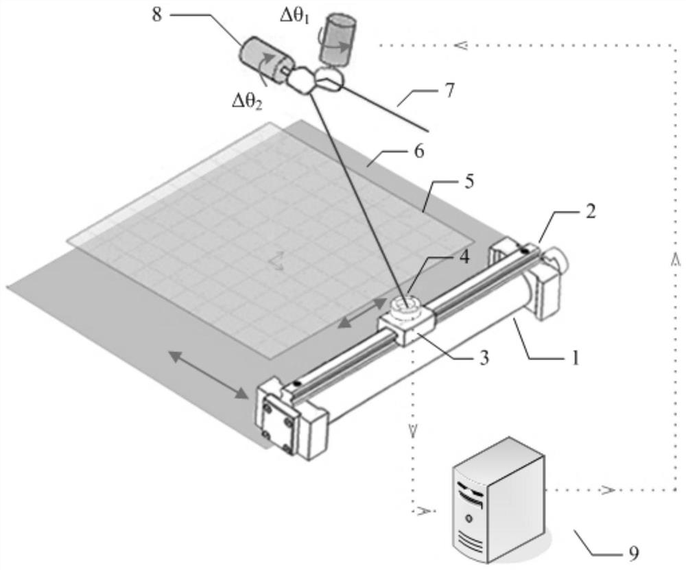
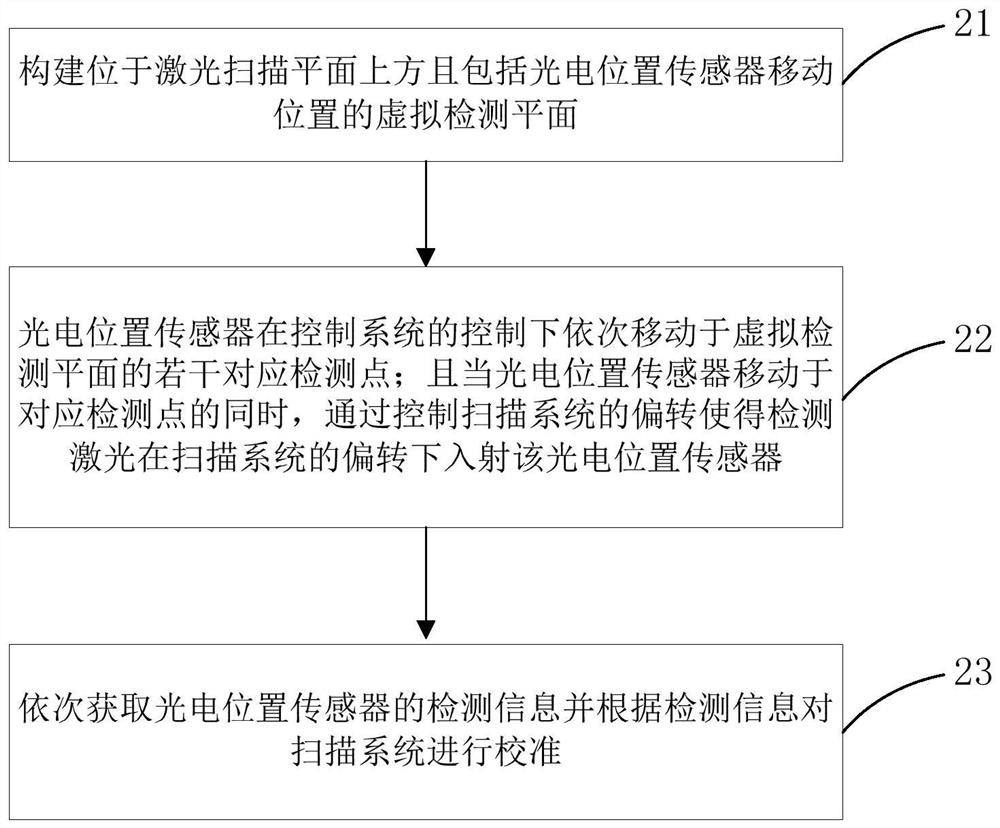
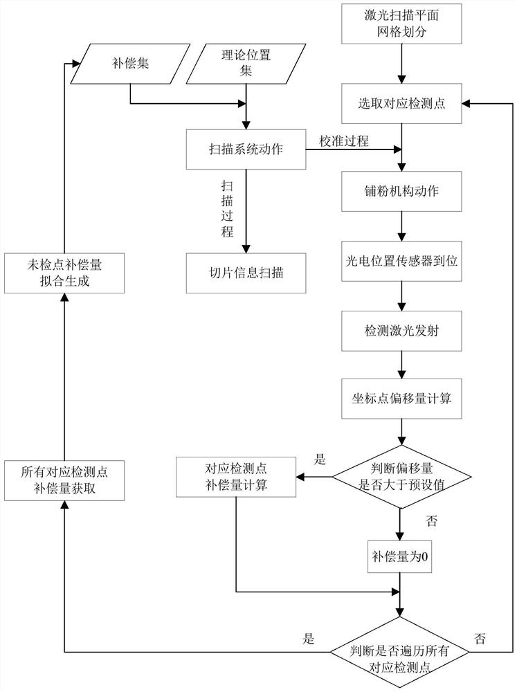
The invention discloses a calibration device for a scanning system and a calibration method of the calibration device. The calibration device comprises a detection laser, a control system and a photoelectric position sensor which is arranged at the top of a powder spreading mechanism and can move in the direction perpendicular to the powder spreading direction; the photoelectric position sensor sequentially moves to a plurality of corresponding detection points under the control of the control system; and when the photoelectric position sensor moves to the corresponding detection points, the deflection of the scanning system is controlled to enable the detection laser to enter the photoelectric position sensor under the deflection of the scanning system, the detection information of the photoelectric position sensor is obtained in sequence, and the scanning system is calibrated according to the detection information. Only the photoelectric position sensor needs to be installed on the existing powder spreading mechanism, automatic calibration can be conducted in combination with software; and the calibration device is simple in structure and low in cost; errors caused by a large amount of manual operation are avoided, and good stability and precision are achieved.

Description

technical field [0001] The invention relates to the technical field of three-dimensional object manufacturing, in particular to a calibration device for a scanning system and a calibration method thereof. Background technique [0002] As one of the additive manufacturing technologies, the basic process of selective laser melting technology is: the powder supply cylinder is raised by one layer thickness to send a certain amount of powder to the working area, the piston or substrate of the forming cylinder is lowered by one layer thickness, and the powder is spread The mechanism spreads a layer of powder material on the base plate of the forming cylinder or the upper surface of the formed part, and the vibrating mirror system controls the laser to scan the solid part of the powder layer according to the cross-sectional profile of the layer, so that the powder melts and connects with the formed part below Achieve bonding. Repeat the above steps until several layers are scanned...

Claims


Application Information

Patent Timeline
IPC IPC(8): G01B11/24G01B11/00
CPCG01B11/24G01B11/002
Inventor 彭伟姜源源鲍光
Owner HUNAN FARSOON HIGH TECH CO LTD
Learn More