Polycrystalline silicon crusher with bar conveying device
A conveying device and polysilicon technology, which is applied in grain processing and other directions, can solve the problems of workers' health hazards and low crushing efficiency.
- Summary
- Abstract
- Description
- Claims
- Application Information
AI Technical Summary
Problems solved by technology
Method used
Image
Examples
Embodiment 1
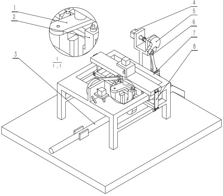
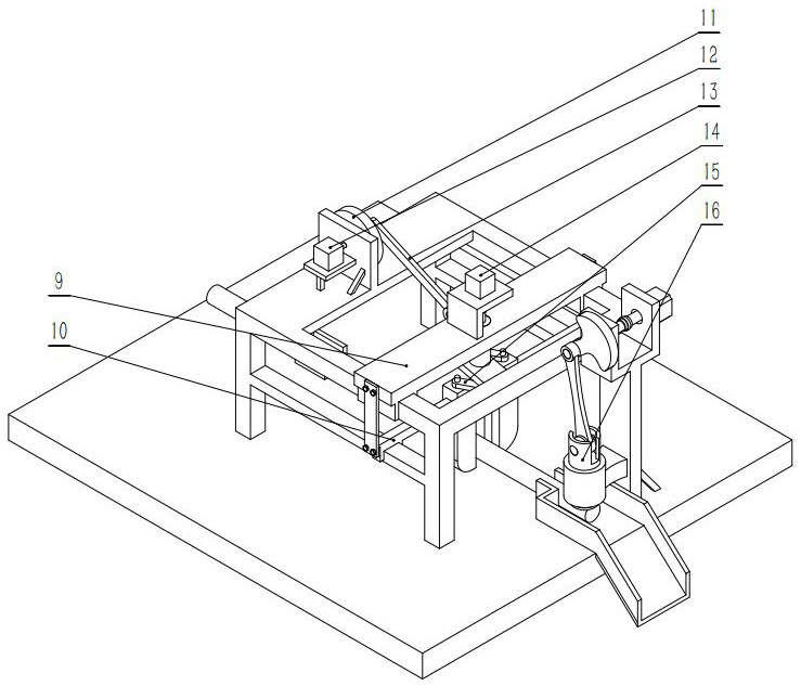
[0017] refer to figure 1 , figure 2 , image 3 , Figure 4 As shown, a polysilicon crusher with a bar material conveying device includes a frame 7, a bar material pushing mechanism, a bar material clamping device, and a polysilicon crushing device. It is characterized in that the bar material pushing mechanism is installed on the front of the frame 7 At the rear, the bar clamping mechanism is located in the middle of the frame 7, and the polysilicon crushing device is located in front of the frame 7.
Embodiment 2
[0019] The difference between this example and Embodiment 1 is that the bar push mechanism includes a push motor 12, a push crank 11, a push-pull connecting rod 13 and a sliding support plate 9, and the push motor 12 is installed on the right rear of the frame, and the push crank 11 center Installed on the rear of the frame 7 through the rotating shaft, one end of the push-pull connecting rod 13 is connected with the push crank 11, and the other end is installed on the rear of the sliding support plate 9.
Embodiment 3
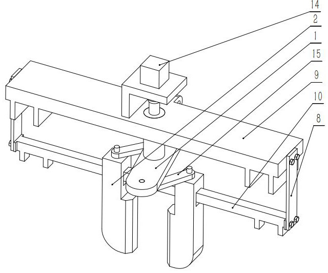
[0021] The difference between this example and Embodiment 1 is that the bar clamping device includes a sliding support plate 9, a clamping motor 14, a rotating clamping disc 1, a clamping link 15, a sliding clamping claw 2, and a sliding support guide rail 10 And the fixed plate 8, the clamping motor 14 is installed on the top of the sliding support plate 9, the rotating clamping disc is connected with the clamping motor 14 through a coupling and installed in the middle of the sliding supporting plate, one end of the clamping link 15 is connected with the rotating clamp The tight disc 1 is connected, and the other end is connected with the top of the sliding clamping claw 2, the top of the sliding clamping claw 2 is connected with the clamping link 15 and installed in the middle of the sliding support guide rail 10, and one end of the fixing plate 8 is fixed on the The side of sliding supporting plate 9, the other end is fixed on the side of sliding supporting guide rail 10 by ...
PUM
 Abstract
Description
Claims
Application Information
 - R&D
- Intellectual Property
- Life Sciences
- Materials
- Tech Scout
- Unparalleled Data Quality
- Higher Quality Content
- 60% Fewer Hallucinations
Browse by: Latest US Patents, China's latest patents, Technical Efficacy Thesaurus, Application Domain, Technology Topic, Popular Technical Reports.
© 2025 PatSnap. All rights reserved.Legal|Privacy policy|Modern Slavery Act Transparency Statement|Sitemap|About US| Contact US: help@patsnap.com


