Novel magnetic electrolytic composite polishing head

A compound polishing and polishing head technology, which is applied in the field of polishing technology and processing technology, can solve the problems of weak magnetic field strength, small size of polishing head, and the influence of magnetic electrolysis compound polishing, and achieve the effect of convenient magnetic field strength, convenient control and flexible solution

Inactive Publication Date: 2020-10-30
TIANSHUI NORMAL UNIV
View PDF9 Cites 1 Cited by
  • Summary
  • Abstract
  • Description
  • Claims
  • Application Information

AI Technical Summary

Problems solved by technology

[0002] Polishing technology refers to the use of mechanical, chemical or electrochemical effects to reduce the surface roughness of the workpiece to obtain a bright and smooth surface, and the use of polishing tools and abrasive particles or other polishing media to modify the surface of the workpiece; In the magnetic electrolytic compound polishing, the direction of the magnetic field is very important, and the static magnetic field perpendicular to the direction of the electric field is easy to realize. Therefore, in the traditional magnetic electrolytic compound polishing, a static magnetic field perpendicular to the electric field is often added, but the volume of the traditional polishing head is very small. Small, the magnetic field strength is also very weak, the influence on the magnetic electrolytic composite polishing is limited, the polishing quality is not ideal, the magnetic field direction and magnetic field size of this kind of polishing head cannot be changed according to the polishing requirements

Method used


Image

  • Novel magnetic electrolytic composite polishing head
  • Novel magnetic electrolytic composite polishing head

Examples


Embodiment Construction

[0010] Below in conjunction with accompanying drawing, parts and effects thereof of the present invention are described:

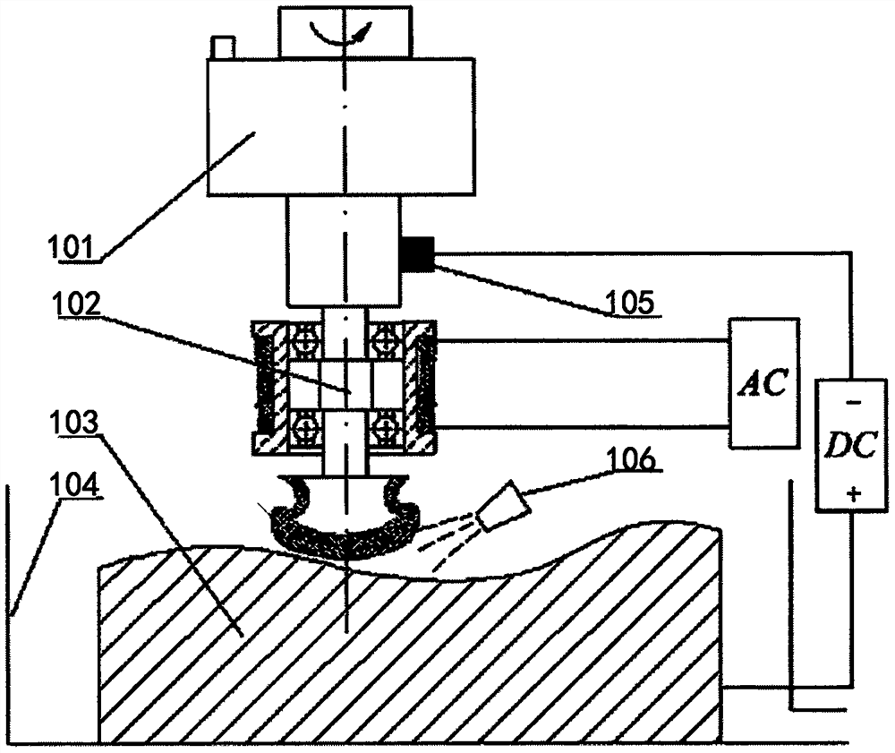
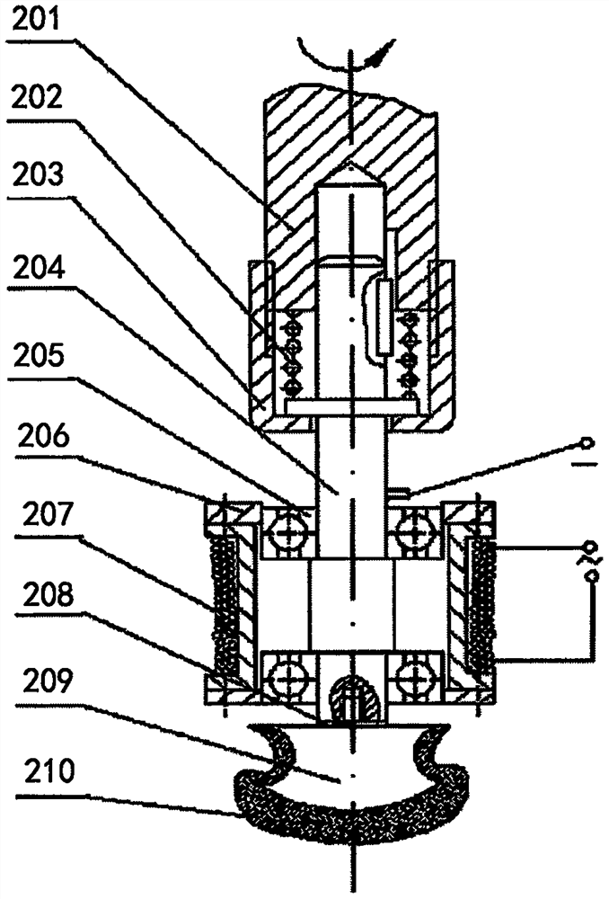
[0011] Such as figure 1 , figure 2 As shown, a novel magnetic electrolytic composite polishing head includes a magnetic electrolytic composite polishing head 102 and a speed increasing device 101 . Wherein the rear handle 201, the shaft 204, the electromagnet 207, and the polishing head 209 are all installed in the magnetic electrolytic composite polishing head 102.

[0012] The above-mentioned rear handle 201 is connected with the shaft 204 by an adjustment sleeve 203, and a spring 202 is installed, the rear handle 201 is pressed above the spring 203, and the adjustment sleeve 203 is wrapped around the rear handle 201, the spring 202, and the shaft 204, thereby playing The function of the flexible connection between the rear handle 201 and the shaft 204.

[0013] The above-mentioned electromagnet 207 is connected with the shaft 204 by means of the bea...


PUM


Abstract

The invention provides a novel magnetic electrolytic composite polishing head. According to the technical scheme, the novel magnetic electrolytic composite polishing head comprises a rear handle, a shaft, an electromagnet, a polishing head and a speed increasing device, wherein the rear handle is connected with an adjusting sleeve for the shaft, and a spring is installed on the rear handle; the electromagnet and the shaft are connected with a retaining ring through a bearing, and the bearing is installed to realize that when the shaft rotates, the electromagnet is not affected by the rotation;and the shaft is provided with an electric brush, the polishing head is arranged at one end of the shaft, and a washer is installed during connecting, and the polishing head is provided with a polishing section. When the electrolytic composite polishing head works, the rear handle is connected with a machine tool through the speed increasing device, so that the magnetic electrolytic composite polishing head is arranged on the machine tool; during working, a workpiece to be machine is connected to the positive pole of a direct current power supply, the electric brush on the shaft is connectedto the negative pole of the direct current power supply, the electromagnet is connected to an alternating current power supply, the machine tool is started, and an electrolyte nozzle sprays the electrolyte to realize polishing of the workpiece.

Description

technical field [0001] The invention relates to a novel magnetic electrolytic composite polishing head, which is suitable for convenient installation of numerical control machine tools and can effectively improve the effect and efficiency of magnetic electrolytic composite polishing. The invention relates to the field of polishing technology and processing technology. Background technique [0002] Polishing technology refers to the use of mechanical, chemical or electrochemical effects to reduce the surface roughness of the workpiece to obtain a bright and smooth surface, and the use of polishing tools and abrasive particles or other polishing media to modify the surface of the workpiece; In the magnetic electrolytic compound polishing, the direction of the magnetic field is very important, and the static magnetic field perpendicular to the direction of the electric field is easy to realize. Therefore, in the traditional magnetic electrolytic compound polishing, a static magn...

Claims


Application Information

Patent Timeline
Patent Type & Authority Applications(China)
IPC IPC(8): B23H5/08B23H11/00
CPCB23H5/08B23H11/00
Inventor 时立民
Owner TIANSHUI NORMAL UNIV
Why Eureka
Try Eureka