MIG/MAG electric-arc motion track control method

A technology of motion trajectory and control method, which is applied in arc welding equipment, manufacturing tools, welding equipment, etc., can solve the problems of asymmetric melting of welding pool, poor anti-interference ability, large randomness, etc., and achieve changing crystallization direction, Improving the quality of weld seam and suppressing porosity

Active Publication Date: 2020-10-30
SHANGHAI DIANJI UNIV
View PDF7 Cites 0 Cited by
  • Summary
  • Abstract
  • Description
  • Claims
  • Application Information

AI Technical Summary

Problems solved by technology

Although electromagnetically controlled arc trajectory can realize the rotation and offset of the arc, the current application is mainly a low-intensity stable magnetic field, which leads to asymmetrical melting of the welding pool and cannot precisely control the arc trajectory and frequency.
Free state arc trajectory movement is relatively random, and the ability to resist external interference is poor
None of the above methods can achieve precise control of the arc trajectory

Method used


Image

  • MIG/MAG electric-arc motion track control method
  • MIG/MAG electric-arc motion track control method
  • MIG/MAG electric-arc motion track control method

Examples


Embodiment

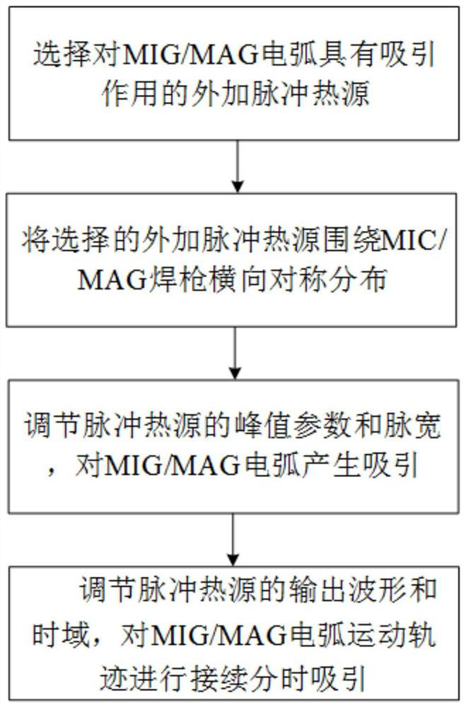
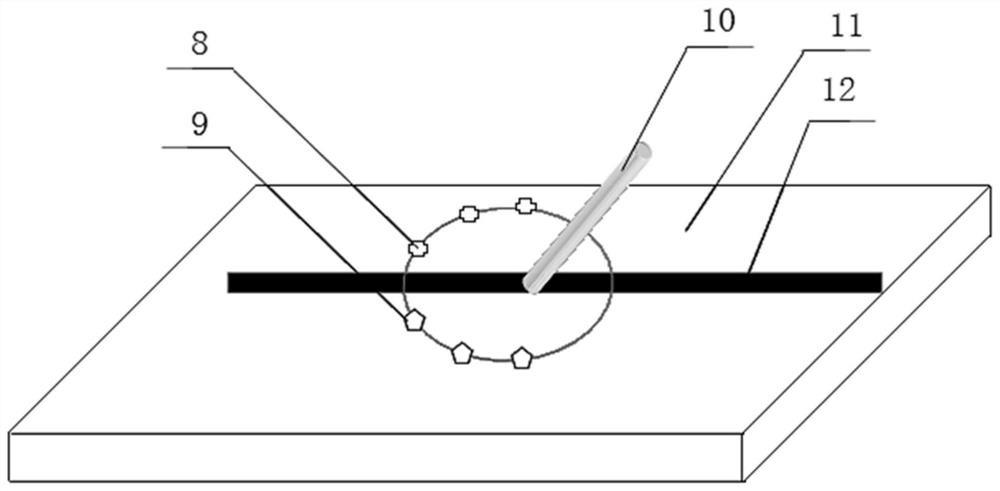
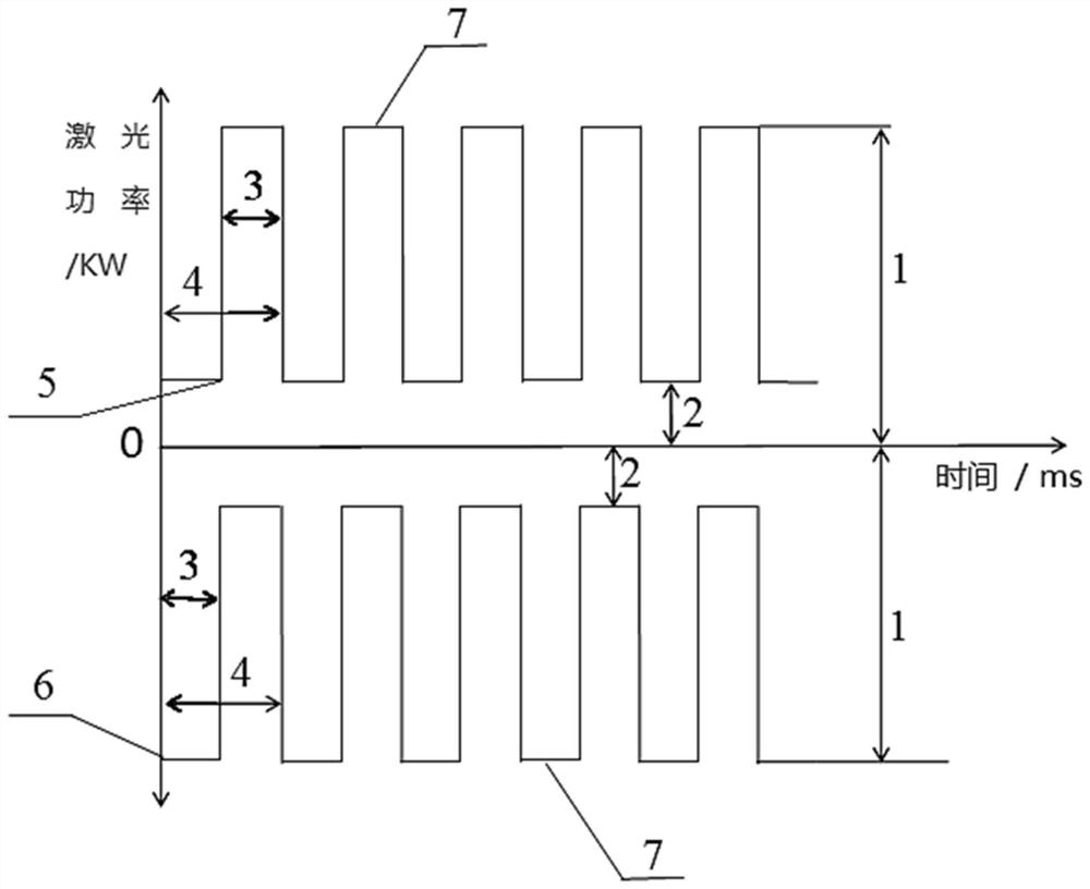
[0024] The invention relates to a MIG / MAG arc motion trajectory control method. During welding, the MIG / MAG arc motion trajectory is controlled by the action point of a pulse heat source, and the time-sharing output characteristics of the pulse heat source are used to adjust the MIG / MAG arc motion trajectory. , according to the number, position and pulse parameters of the external pulse heat source, the precise control of the MIG / MAG arc motion trajectory can be realized. The specific technical steps of the method include:

[0025] Step 1. Select an external pulse heat source that has an attractive effect on the MIG / MAG arc. The number of additional pulse heat sources includes 2, 4 or 6. The number of heat sources is selected according to the hardware conditions and the accuracy of the arc motion trajectory. The greater the number of heat sources, the higher the control accuracy of the arc motion trajectory. Pulsed heat sources can be lasers, plasmas or electron beams.

[0...


PUM


Abstract

The invention relates to an MIG/MAG electric-arc motion track control method which comprises the following steps: 1, selecting external pulse heat sources with attraction effect on an MIG/MAG electricarc to be controlled; 2, transversely and symmetrically arranging selected external pulse heat sources around an MIG/MAG welding gun to be controlled; 3, regulating pulse parameters of the external pulse heat sources, and generating attraction on the MIG/MAG electric arc to be controlled; and 4, regulating output waveforms and time domains of the external pulse heat sources, and performing continuous time-shared attraction on the MIG/MAG electric-arc motion track to be controlled. Compared with the prior art, the MIG/MAG electric-arc motion track control method can intervene a weld pool morphology, a welded weld pool temperature gradient and droplet stress more precisely, has the advantages of refining crystalline grains, changing a crystalline grain crystallization direction, reducing segregation, restraining gas holes and the like, and is of great significance in improving welding seam quality.

Description

technical field [0001] The invention relates to the technical field of welding, in particular to a method for controlling the motion trajectory of a MIG / MAG arc. Background technique [0002] At present, the arc movement trajectory during welding mainly includes: 1) synchronous welding torch movement trajectory (swing welding, rotary welding), the arc movement trajectory is macroscopically the same as the welding torch movement trajectory, and microscopically belongs to a random state trajectory; 2) high-energy beam heat source induced movement trajectory ( Laser, plasma, electron beam), the arc is biased to the action point of the high-energy beam, and the arc stability is enhanced; 3) Electromagnetic control of the motion trajectory, by changing the magnetic field direction or external magnetic field to control the arc action trajectory, the arc can be rotated and oscillated; 4) Free State trajectory, conventional single arc welding arc, no external mechanical, electromagn...

Claims


Application Information

Patent Timeline
Patent Type & Authority Applications(China)
IPC IPC(8): B23K9/12B23K9/173B23K9/32
CPCB23K9/126B23K9/173B23K9/32
Inventor 刘西洋杨淼森张旺郭彦兵陆斌锋方乃文
Owner SHANGHAI DIANJI UNIV
Why Eureka
Try Eureka