
Plastic injection molding machining mold facilitating heat dissipation and workpiece arrangement

A technology of injection molding processing and mould, which is applied in the field of molds for plastic injection molding processing, and can solve problems such as waste of time, semi-solid residue, and waste of injection molding raw materials

Inactive Publication Date: 2020-10-30
潘武杰
View PDF11 Cites 3 Cited by
  • Summary
  • Abstract
  • Description
  • Claims
  • Application Information

AI Technical Summary

Problems solved by technology

[0007] In order to solve the above-mentioned technical problems, the present invention provides a mold for plastic injection molding that is convenient for heat dissipation and workpiece arrangement, to solve the existing problem that during the injection molding process, the cooling gas inside the mold base near the inner side of the mold base absorbs heat It is willing to increase the temperature quickly, but the existing device cannot realize the mixing of cooling gas in the mold base by means of mechanical linkage to improve the cooling effect; moreover, after the injection molding is completed, the tail of the plastic part is easy to form a semi-solid residue, and the The existing device cannot realize automatic close-distance cutting after injection molding is completed. On the one hand, manual cutting is a waste of time and injection molding raw materials; finally, the sliding support structure of the existing device cannot automatically clean and discharge slag in time

Method used


Image

  • Plastic injection molding machining mold facilitating heat dissipation and workpiece arrangement
  • Plastic injection molding machining mold facilitating heat dissipation and workpiece arrangement
  • Plastic injection molding machining mold facilitating heat dissipation and workpiece arrangement

Examples


Embodiment

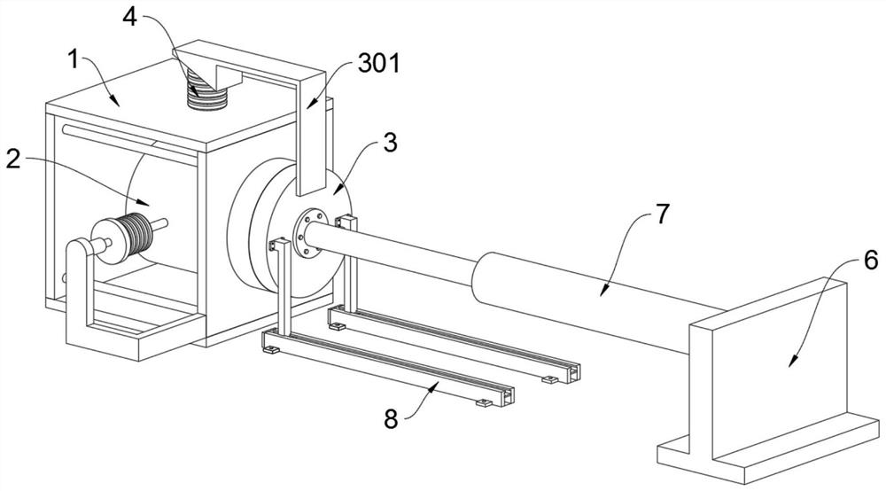
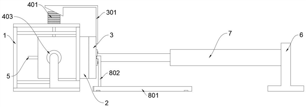
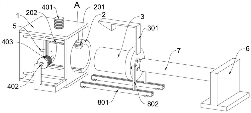
[0033] as attached figure 1 to attach Figure 8 Shown:

[0034] The invention provides a mold for plastic injection molding which is convenient for heat dissipation and workpiece arrangement, which comprises a frame body 1; Also be provided with feed pipe 5; Refer to as Figure 7 and Figure 8 , the feed tank 503 has an L-shaped structure, and a number of circulation holes 50401 are opened in a circular array on the retaining ring 504; when the liquid is injected, the locking rod 505 moves forward under the thrust of the liquid to contact the head end of the pipe body 501, At this time, the elastic member 506 is in a compressed state, and at this time, the feeding groove 503 is in a communication state with the pipe body 501, thereby maintaining the normal circulation of the plastic liquid; refer to as Figure 7 and Figure 8 , when the liquid injection is finished, the locking lever 505 is pushed back to the original position by the elastic force of the elastic member 50...


PUM


Abstract

The invention provides a plastic injection molding machining mold facilitating heat dissipation and workpiece arrangement, relates to the field of injection molding machining, and solves the problem that an existing device cannot achieve mixing of cooling gas in a mold female base through a mechanical linkage means to improve the cooling effect, the existing device cannot achieve automatic close-range cutting after injection molding is completed, on the one hand, manual cutting wastes time, and injection molding raw material is wasted. The plastic injection molding machining mold facilitatingheat dissipation and workpiece arrangement comprises a frame body, and the mold female base is welded on the frame body; plastic liquid is jetted into the mold female base through a feeding pipe, at the moment, a locking rod moves forwards to make contact with the head end of the pipe body under the thrust effect of the liquid, an elastic piece is in a compressed state at the moment, a feeding groove is in communication with the pipe body at the moment, and therefore the normal distribution of the plastic liquid is kept; after liquid injection is finished, the locking rod is pushed by the elastic force of the elastic piece to return to the initial position, and the pipe body returns to the initial sealing state.

Description

technical field [0001] The invention belongs to the technical field of injection molding, and more specifically relates to a mold for plastic injection molding which is convenient for heat dissipation and finishing of workpieces. Background technique [0002] Injection molding is a processing method used in the mass production of certain parts with complex shapes. Specifically, it refers to injecting heated and melted materials into a mold cavity under high pressure, and after cooling and solidifying, molded products are obtained. [0003] For example, the application number: CN201410436683.5, the invention provides an injection mold for processing products with oblique holes, which belongs to the field of mold technology. The injection mold includes a fixed mold middle plate, a movable mold middle plate, and a movable mold seat plate. There is a push component movable between the movable mold seat plate; a straight top block connected with the push component is embedded in...

Claims


Application Information

Patent Timeline
IPC IPC(8): B29C45/73B29C45/66B29C45/17B29C45/23
CPCB29C45/7312B29C45/66B29C45/1753B29C45/23
Inventor 潘武杰
Owner 潘武杰
Learn More