

Heavy-duty carrying equipment and construction method thereof
A heavy-duty, equipment-based technology that is applied in excavation, transportation and packaging, and infrastructure engineering. It can solve problems such as uncontrollable installation accuracy, time-consuming and labor-consuming installation, and earthwork construction period occupied by installation, so as to improve economy and environmental protection. , Improve the efficiency of excavation and shorten the construction period
- Summary
- Abstract
- Description
- Claims
- Application Information
AI Technical Summary
Problems solved by technology
Method used
Image

Examples
Embodiment 1
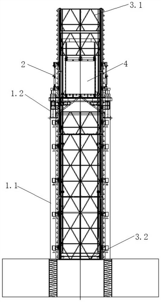
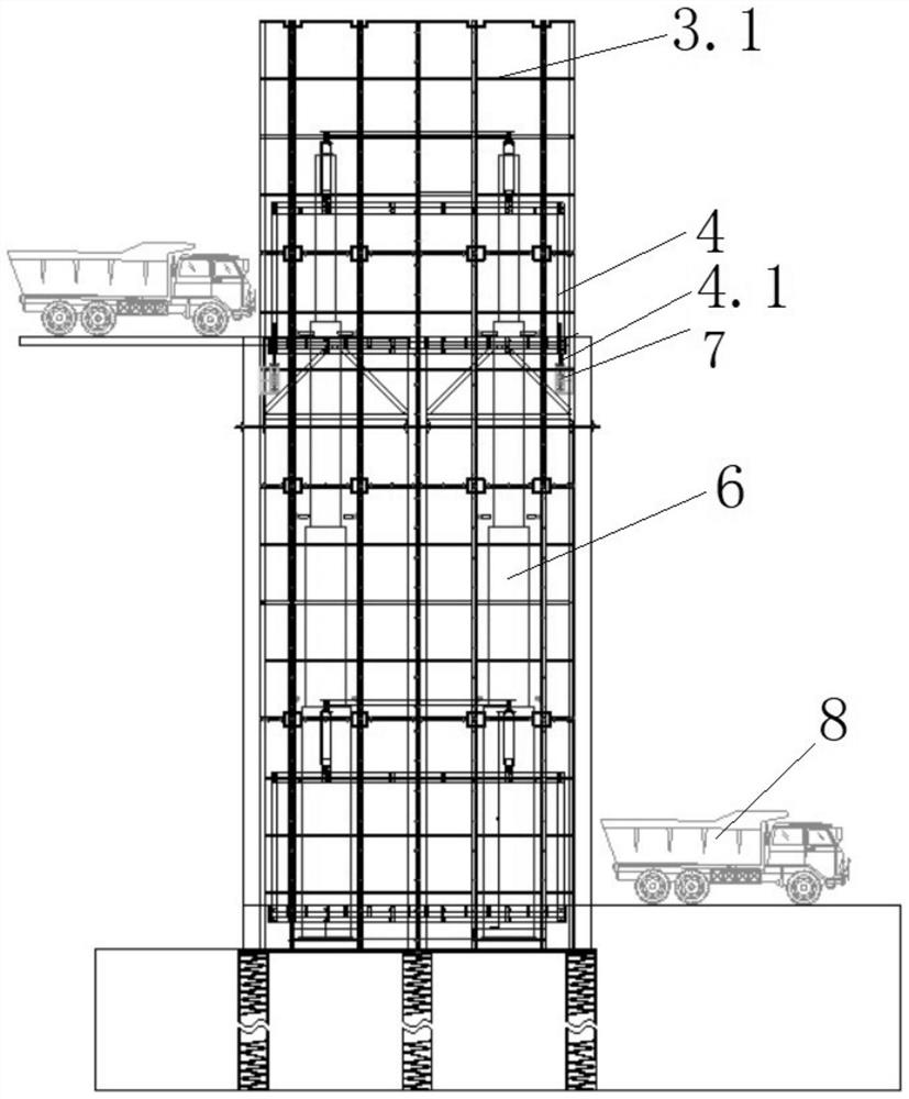
[0036] The present invention provides a kind of heavy-duty carrying equipment, such as Figure 1 to Figure 4 As shown, it includes skeleton attachment structure, integral down-moving device and heavy-duty earth-lifting facility.
[0037] The skeleton attachment structure is composed of the lower load-bearing pile frame structure 1.1 and the top support structure 1.2. The top support structure 1.2 is detachably connected to the lower load-bearing pile frame structure 1.1 in the circumferential direction, and will be disassembled and turned around after the project is over.
[0038] The overall down-moving device is arranged between the top support structure 1.2 and the heavy-duty soil lifting facility, and includes multiple groups of down-moving mechanisms 2 assembled on the top support structure 1.2. For the detailed structure of the overall down-moving device, see the patent application CN201911029544.X.
[0039] The heavy-duty soil lifting facility includes a peripheral ske...
Embodiment 2
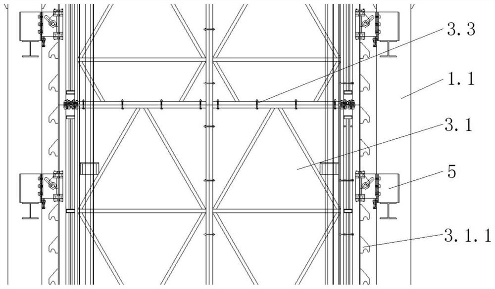
[0057] The principle and structure of this embodiment are similar to Embodiment 1, the difference is that: Figure 6 and Figure 7 As shown, the downward movement mechanism 2 includes an upper support 2.1 (equivalent to the frame bracket), a downward movement cylinder 2.2 (also can be other lifting devices), a lower support 2.3 (equal to the load-bearing support) and a bearing shaft 2.5 . The upper and lower supports are provided with oblique oblong holes 2.4, and each of the oblique oblong holes 2.4 is provided with the load-bearing shaft 2.5. The position of the oblique oblong hole 2.4 is such that when the load-bearing shaft 2.5 is located in the lower half, it is matched with the load-bearing structure 3.1.1 of the bracket. 1 Disengage from the onboard. The load-bearing shaft 2.5 can be automatically located at the load-bearing point after being converted in the oblong hole 2.4 when moving down, and the upper and lower supports alternately switch the bearing capacity wh...
PUM
 Abstract
Description
Claims
Application Information