Supercharge Your Innovation With Domain-Expert AI Agents!

Heat dissipation structure of centrifugal pump

A heat dissipation structure and centrifugal pump technology, applied in the mechanical field, can solve problems such as affecting bearing life and reducing rotor rotation accuracy, and achieve the effects of extending structural life, prolonging aging speed, and improving heat dissipation efficiency.

Inactive Publication Date: 2020-10-30
HANGZHOU MUYE MASCH TECH CO LTD
View PDF1 Cites 0 Cited by
  • Summary
  • Abstract
  • Description
  • Claims
  • Application Information

AI Technical Summary

Problems solved by technology

[0004] In the above-mentioned centrifugal pump, the two ends of the rotor are the driving end and the supporting end, and both ends are supported by bearings. When the rotor rotates at high speed, the contact between the rotor and the bearing and the bearing itself will generate wear and a lot of heat. Not only seriously affect the life of the bearing, but also the rotation accuracy of the rotor will gradually decrease under long-term use

Method used


Image

  • Heat dissipation structure of centrifugal pump
  • Heat dissipation structure of centrifugal pump
  • Heat dissipation structure of centrifugal pump

Examples


Embodiment 1

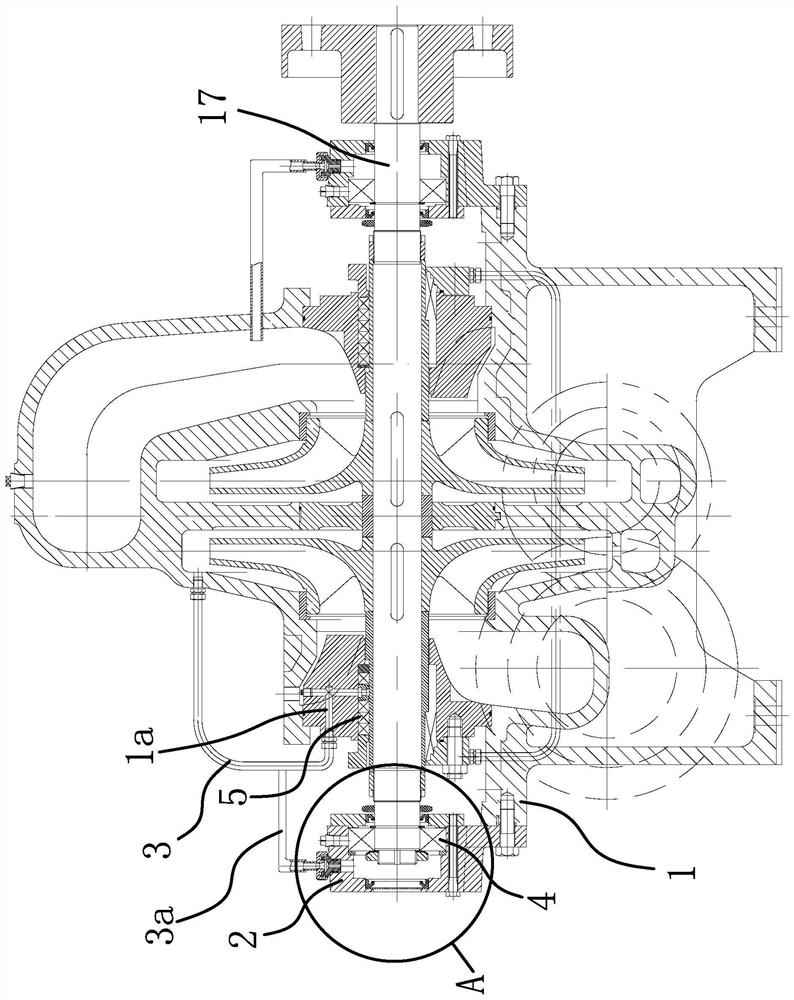
[0028] Such as figure 1 As shown, in the heat dissipation structure of the centrifugal pump, the centrifugal pump includes a pump body 1, a rotor 17 horizontally arranged in the pump body, a barrel body 2 and a flushing pipe 3 arranged outside the pump body 1, and the outer end of the rotor 17 protrudes from the pump body 1 And located in the bucket body 2, and the bucket body 2 and the rotor 17 are connected through the bearing 4. In this embodiment, the preferred type of bearing 4 is a rolling bearing 4 .

[0029] Among them, the outer end of the rotor 17 forms a seal with the pump body 1 through the mechanical seal 5, one end of the flushing pipe 3 communicates with the pump chamber of the pump body 1, and the pump body 1 is provided with a flow channel 1a for flushing the mechanical seal 5, and the flushing pipe 3 The other end communicates with flow channel 1a. In this embodiment, the connection methods of the mechanical seal 5 and the flushing pipe 3 to the flow channe...

Embodiment 2

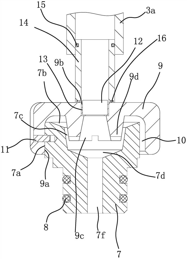
[0037] The structure and principle of this second embodiment are basically the same as that of the first embodiment, except that: one side of the outer wall at the upper end 7 of the oil pipe is a plane 7a, and the inner wall of the cover body 9 has a plane 2 9a that is in close contact with the plane 1 7a , there is threaded hole 2 horizontally running through plane 2 9a, and threaded hole 1 coaxial with threaded hole 2 is provided on plane 1 7a, the same bolt is screwed inside threaded hole 1 and threaded hole 2, and the head of the bolt is located in the cover 9 in vitro.


PUM


Abstract

The invention provides a heat dissipation structure of a centrifugal pump, and belongs to the technical field of machinery. The centrifugal pump comprises a pump body, a rotor which is arranged in thepump body, a barrel body and a flushing pipe, the barrel body and the flushing pipe are arranged outside the pump body, the outer end of the rotor extends out of the pump body and is located in the barrel body, the outer end of the rotor and the pump body form sealing through a mechanical sealing piece, one end of the flushing pipe communicates with a pump cavity of the pump body, a runner for flushing the mechanical sealing element is arranged in the pump body, the other end of the flushing pipe communicates with the runner, one end, close to the pump body, of the barrel body and the rotor form sealing through an oil seal, a closed cavity is formed among the barrel body, the rotor and the oil seal, an oil filling hole which communicates with the closed cavity is arranged on the upper side of the barrel body in a penetrating mode, an oil pipe is arranged into the upper end of the oil filling hole in an inserted mode, the upper end of the oil pipe extends out of the oil filling hole and extends into a cover body, the oil pipe is detachably and fixedly connected with the cover body, a groove is formed in the top wall of the cover body, an exhaust hole is arranged on the bottom wallof the groove in a penetrating mode, a semiconductor chilling plate and an annular sealing piece are fixedly arranged in the groove, and the semiconductor chilling plate and the annular sealing pieceare matched to seal the exhaust hole. According to the heat dissipation structure of the centrifugal pump, lifetime can be prolonged.

Description

technical field [0001] The invention belongs to the technical field of machinery, and relates to a centrifugal pump, in particular to a heat dissipation structure of a centrifugal pump. Background technique [0002] Centrifugal pumps work by rotating the impeller to cause the water to move centrifugally. [0003] Existing centrifugal pumps, such as a horizontal multi-stage centrifugal pump disclosed in the Chinese Patent Library [Application No.: 201510865619.3], include an elastic coupling, a rotor connected to the elastic coupling, a rolling bearing coaxial with the rotor, and a rolling bearing Connected pump body, the pump body includes a suction section, a guide vane connected to the suction section, a plurality of middle sections connected to the guide vane, a final guide vane connected to the middle section, a discharge section connected to the final guide vane, and a water seal pipe And the balance return pipe, and a sealing ring is provided between the suction secti...

Claims


Application Information

Patent Timeline
Patent Type & Authority Applications(China)
IPC IPC(8): F04D29/58F04D29/06F04D29/08F04D29/12
CPCF04D29/061F04D29/086F04D29/126F04D29/586F04D29/588
Inventor 张家旸
Owner HANGZHOU MUYE MASCH TECH CO LTD
Features
  • R&D
  • Intellectual Property
  • Life Sciences
  • Materials
  • Tech Scout
  • Unparalleled Data Quality
  • Higher Quality Content
  • 60% Fewer Hallucinations
Learn More