Control method of heat pump system

A control method and heat pump system technology, applied in the direction of heating mode, heating and ventilation control system, heating and ventilation safety system, etc., can solve the problems of poor heating comfort, short heating time, short frosting cycle, etc.

Pending Publication Date: 2020-10-30
GREE ELECTRIC APPLIANCES INC +1
View PDF6 Cites 7 Cited by
  • Summary
  • Abstract
  • Description
  • Claims
  • Application Information

AI Technical Summary

Problems solved by technology

[0004] Most of the existing technologies use defrosting control to reduce the adverse effects of frosting on the outdoor heat exchanger on the performance of the air condi...

Method used


Image

  • Control method of heat pump system
  • Control method of heat pump system
  • Control method of heat pump system

Examples


Embodiment Construction

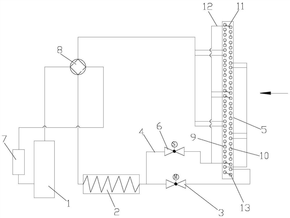
[0078] The direction of the arrow in the figure is the air flow direction.

[0079] see in conjunction figure 1 As shown, according to the embodiment of the present application, the heat pump system includes a compressor 1, an indoor heat exchanger 2, a first throttling device 3, a second throttling device 6, a bypass pipeline 4 and an outdoor heat exchanger 5, so The inner exhaust pipe 9 is connected to the indoor heat exchanger 2 through the bypass pipeline 4, the outer exhaust pipe 10 is connected to the indoor heat exchanger 2 through the main flow, and the first throttling device 3 It is arranged on the segmented main flow between the outer exhaust pipe 10 and the indoor heat exchanger 2, the second throttling device 6 is arranged on the bypass pipeline 4, and the outer exhaust pipe 10 and the The segmented main flow forms the flow path of the outer exhaust pipe 10 , and the flow path of the outer exhaust pipe 10 is connected in parallel with the bypass pipeline 4 and th...


PUM


Abstract

The invention provides a control method of a heat pump system. The control method comprises the steps that operation parameters of the heat pump system are obtained; whether a control condition for delaying frosting is met or not is judged; and when the control condition for delaying frosting is met, the opening degree of a first throttling device and/or the opening degree of a second throttling device are/is controlled to be increased. According to the control method of the heat pump system, the frosting period of the heat pump system can be prolonged, the indoor continuous heat supply time is prolonged, and the indoor heat comfort is improved.

Description

technical field [0001] The application belongs to the technical field of air conditioning, and in particular relates to a control method for a heat pump system. Background technique [0002] When the heat pump air conditioner is heating at low temperature, due to the influence of frosting and defrosting, it will cause large fluctuations in indoor temperature and poor comfort. Therefore, various means are adopted in the prior art to reduce the impact of defrosting on the indoor temperature. [0003] There is an air conditioner in the prior art. By dividing the indoor heat exchanger into two parts (the first indoor heat exchanger and the second indoor heat exchanger), when defrosting is required on the outdoor side, the four-way valve switches to defrost. After passing through the outdoor heat exchanger, the high-temperature refrigerant first flows through the second indoor heat exchanger, then flows through the expansion valve, and then flows through the first indoor heat e...

Claims


Application Information

Patent Timeline
IPC IPC(8): F24F11/42F24F11/871F24F11/61F24F11/86F24F11/70F24F11/83
CPCF24F11/42F24F11/871F24F11/61F24F11/86F24F11/70F24F11/83F25B13/00F24F2110/12F25B2700/11F25B47/025F25B2600/2513F25B2313/0315F25B2600/021F25B2400/01F25B2313/0314F25B2313/0293F25B2313/0294F25B2313/0253F25B2313/005F25B2313/02522F25B2400/0409Y02B30/70
Inventor 陈姣何振健林金煌冯青龙秦晓柯戴志炜
Owner GREE ELECTRIC APPLIANCES INC
Why Eureka
Try Eureka