Circuit Breaker Arrangement in an Indicating Arrangement in an Electrically Powered Stapler

a technology of circuit breakers and indicating arrangements, which is applied in the field of linear motors, can solve problems such as errors in measured values, and achieve the effects of preventing thermal deformation of surrounding members and devices, reducing measurement errors of measuring instruments, and high heat absorption characteristics

Active Publication Date: 2008-09-04
NIKON CORP
View PDF26 Cites 9 Cited by
  • Summary
  • Abstract
  • Description
  • Claims
  • Application Information

AI Technical Summary

Benefits of technology

[0017]According to the present invention, active coolant with high heat absorption characteristics can be used while maintaining the electric insulating properties, even when the motor is driven with high thrust, the rise in the surface temperature of the coil unit can be inhibited. The result is that measurement errors of measuring instruments and thermal deformation of surrounding members and devices can be prevented according to the present invention.

Problems solved by technology

For example, the heat release from the linear motor may cause thermal deformation in the surrounding members and devices, and may vary the air temperature in the light path of an interferometer used for detecting the stage position, and cause errors in the measured values.

Method used


Image

  • Circuit Breaker Arrangement in an Indicating Arrangement in an Electrically Powered Stapler
  • Circuit Breaker Arrangement in an Indicating Arrangement in an Electrically Powered Stapler
  • Circuit Breaker Arrangement in an Indicating Arrangement in an Electrically Powered Stapler

Examples


first embodiment

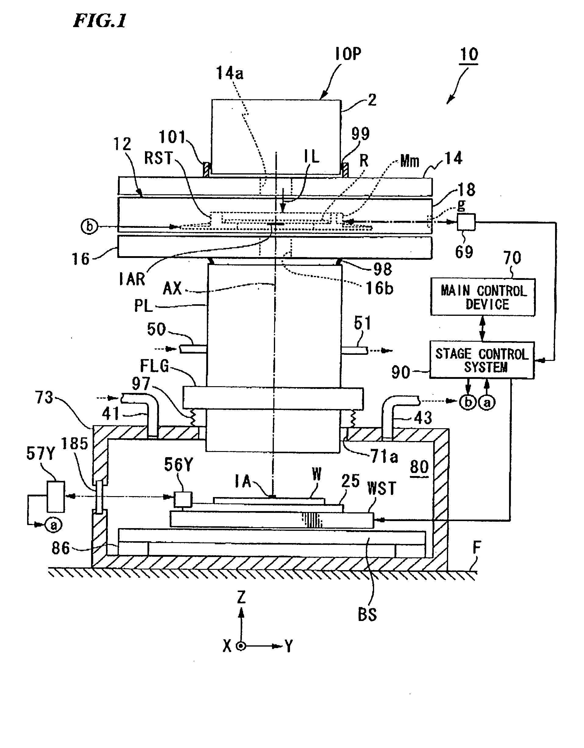
[0036]FIG. 1 shows the schematic configuration of the projection exposure apparatus (=exposure apparatus) 10 of the present embodiment. In FIG. 1, the Z axis is taken parallel to the optical axis AX of the projection optical system PL provided in the projection exposure apparatus 10, the Y axis is taken in the scanning direction of the reticle and wafer (described in detail hereafter) during scanning exposure in the plane perpendicular to the Z axis, and the X axis is taken in the non-scanning direction perpendicular to the scanning direction, for the purpose of explanations.

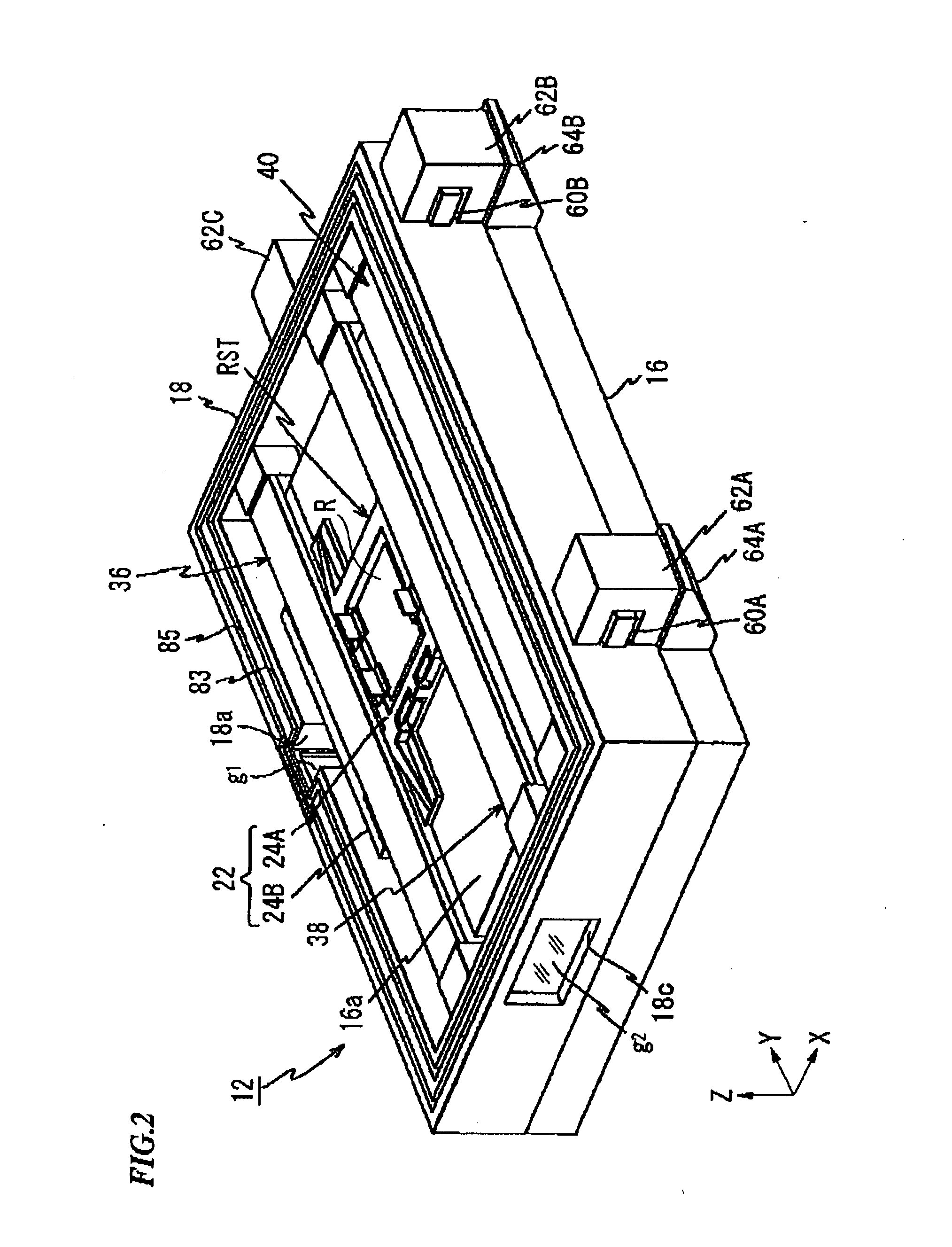
[0037]The projection exposure apparatus 10 of the present embodiment is provided with an illuminating optical system unit IOP, a reticle stage apparatus 12 used as a stage apparatus for driving the reticle R formed on a circuit pattern as a mask for a specific stroke in the Y direction and for fine driving it in the X direction, the Y direction and the θz direction (direction of rotation around the Z axis), a pr...

second embodiment

[0109]Next the second embodiment of the linear motor related to the present invention is described hereafter referring to FIG. 8A and FIG. 8B. Elements in these figures, which are the same as the elements forming the first embodiment shown in FIG. 7A and FIG. 7B, are affixed the same reference numerals and their explanations are omitted.

[0110]In FIG. 8A and FIG. 8B, the illustration of frame 142 is omitted and only the coil unit 141 is illustrated. Also, for the sake of convenience, the coil unit 141 shown in FIG. 8A and FIG. 8B is illustrated in the form of a rectangular cross section after omitting the flange.

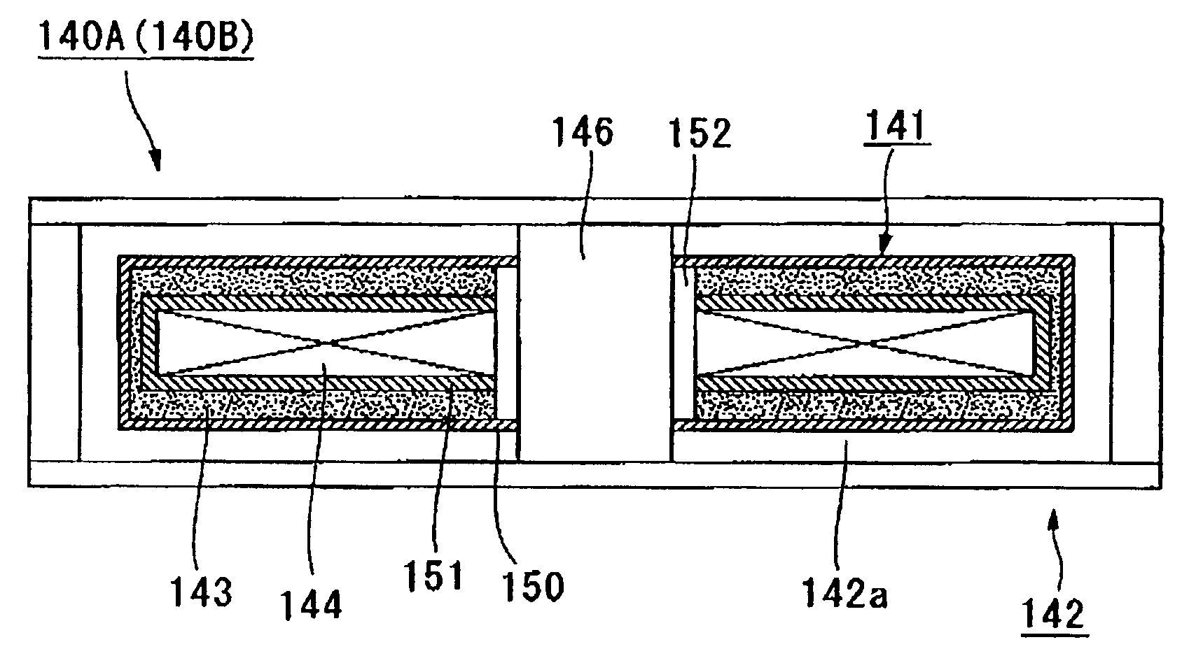
[0111]FIG. 8A is a plan view of the coil unit 141, while FIG. 8B is a front cross section view.

[0112]The coil unit 141 of the present embodiment has a coil body 144 that is covered by cylindrical thin plating 151. This thin plating 151 is formed by very thin (for example, a thickness of 0.1 mm) glass epoxy resin with no pinholes in the shape of a rectangular cross section fra...

third embodiment

[0115]Next, the third embodiment of the linear motor related to the present invention is described hereafter referring to FIG. 9. In this figure, elements that are the same in the first embodiment shown in FIG. 7A and FIG. 7B, and in the second embodiment shown in FIG. 8A and FIG. 8B, are affixed the same reference numerals and their explanations are omitted.

[0116]The coil unit 141 in the present embodiment is fixed to the same 142 via the core member 146 of the coil body 144. In this case, the entire coil body 144 including the core member 146 cannot be covered by the cylindrical thin plating 151, as in the configuration of the second embodiment. For this reason, only the coil body 144 is covered by the thin plating 151 whereupon the mold layer 143 and the waterproofing layer 150 are formed. However, with this configuration, if the adhesion between the core member 146 and the mold layer 143, or between the core member 146 and the waterproofing layer 150 is not satisfactory, coolant...


PUM

PropertyMeasurementUnit
wavelengthaaaaaaaaaa

Abstract

A linear motor with high heat recovery efficiency that inhibits the rise in surface temperature is offered. The linear motor is disposed in a surrounding member (142) and facing a flow passage (142a) of a liquid for regulating temperature, and is provided with a coil unit (141) having at least a part thereof in contact with the liquid. The coil unit (141) is provided with a coil body (144), a mold layer (143) that covers the coil body and holds it in specific form, and a liquid protection layer (150) that covers the mold layer (143) and has liquid protection properties.

Description

TECHNICAL FIELD[0001]The present invention relates to linear motor provided with a coolant coil unit, stage apparatus used as a drive device for this linear motor, and exposure apparatus for projecting the mask pattern on to a substrate using a moving stage for driving the linear motor.[0002]This application claims priority to Japanese Patent Application No. 2004-289924, filed Oct. 1, 2004, the contents of which are incorporated herein by reference.BACKGROUND ART[0003]For example, a linear motor is frequently used in an exposure apparatus used in the production of semiconductor elements, liquid-crystal display elements and the like, as a drive device that can drive without contact a reticle stage wherein a mask (reticle and the like) is placed and held, or a wafer stage wherein a photosensitive substrate (wafer, substrate and the like) is placed and held. Although heat-releasing coil body is used in this kind of linear motor when current is passed, generally, the exposure apparatus ...

Claims


Application Information

Patent Timeline
Patent Type & Authority Applications(United States)
IPC IPC(8): H02K41/02H02K3/30H02K3/32G03F7/20
CPCG03F7/70758G03F7/70858H02K9/19H02K16/00H02K41/031H02K2201/18H02K3/47H02K9/22H02K9/227H02K9/197H02K41/02G03F7/70716G03F7/70875G03F7/70725
Inventor MORIMOTO, SHIGERUKOMINAMI, TADAHIRO
Owner NIKON CORP
Why Eureka
Try Eureka