Heat pipe using solar energy to achieve vacuum light condensation

A solar energy and heat pipe technology, applied in the field of heat pipes, can solve the problems of difficult processing, complicated processing methods, breakage, etc., and achieve the effects of simple and easy system design, ensuring vacuum heat insulation effect, and improving light transmittance.

Active Publication Date: 2014-04-09
NANJING CHENGYUAN SOLAR HEATING +1
View PDF7 Cites 9 Cited by
  • Summary
  • Abstract
  • Description
  • Claims
  • Application Information

AI Technical Summary

Problems solved by technology

[0004] CN102278832A Chinese patent document discloses a medium-high temperature heat collecting tube for internal concentrating solar energy and its manufacturing method. It is to position the reflector 3 in the vacuum chamber through the elastic bracket 8, and the heat-absorbing tube adopts the metal sleeve 5, and the structure is relatively Complicated and difficult to process, although they have high thermal efficiency in theory, we have found in practice that because the inner layer of the vacuum cavity in the medium-high temperature heat collecting tube is in contact with the high-temperature area, and the outer layer is located in the external natural space, during the working process of the product , the temperature difference between the inner and outer layers is generally more than 4-5 times, the inner and outer glass of the vacuum chamber is very easy to form stress concentration at their junction, so that the junction of the inner and outer glass is damaged, thus losing the ability to prevent the inner high temperature area from flowing through the vacuum. Technical advantage of externally diffused heat
[0005] CN202521925U Chinese patent document discloses a kind of internal concentrating light-bearing pressurized solar energy medium and high temperature heat collecting tube, mainly for the complex processing method that the reflecting plate is positioned in the vacuum cavity through the elastic bracket, and the reflective plate is moved to the outside of the vacuum cavity by glass In the sealed cavity constructed by the outer cover tube, this structure is also not solved. Because the temperature difference between the inner and outer layers of the medium and high temperature heat collecting tube is generally more than 4-5 times, it is very easy to form stress concentration at the junction of the inner and outer glass of the vacuum tube, making the inner and outer glass The technical problem of damage to the joint part, and the practical problem that the heat-absorbing tube adopts a metal sleeve, the structure is relatively complicated, and the processing is difficult

Method used


Image

  • Heat pipe using solar energy to achieve vacuum light condensation
  • Heat pipe using solar energy to achieve vacuum light condensation
  • Heat pipe using solar energy to achieve vacuum light condensation

Examples


Embodiment Construction

[0019] The accompanying drawings disclose the specific structures of the embodiments of the present invention without limitation, and the present invention will be further described below in conjunction with the accompanying drawings.

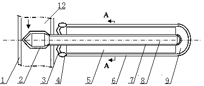
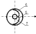
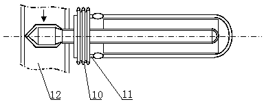
[0020] Depend on figure 1 and figure 2 It can be seen that the present invention includes the heat collecting end and the heat releasing end 2 of the heat pipe, wherein: the heat collecting end includes a light concentrating reflector 5 and an outer tube 6 and a central tube with one end opening, the refrigerant 8 is placed in the sealed central tube, and the outer tube 6 is a glass tube, the open end of the outer tube 6 is provided with an axially deformable metal end cap 3, the inside of the outer tube 6 forms a vacuum-sealed cavity 9, the central tube and the outer tube 6 are coaxially arranged, and one end extends out of the vacuum seal Cavity 9, the central tube in the vacuum-sealed cavity 9 is the heat-absorbing end 7 of the heat pi...


PUM


Abstract

The invention relates to a heat pipe using solar energy to achieve vacuum light condensation. The heat pipe comprises a heat collecting end and a heat exhausting end and is characterized in that the heat collecting end comprises a light condensation reflection board, an outer pipe and a central pipe, wherein one end of the outer pipe is open, refrigerants are arranged in the sealed central pipe, the outer pipe is a glass pipe, the open end of the outer pipe is provided with a metal end cover which can deform in the axial direction, and a vacuum sealed cavity is formed in the outer pipe. The central pipe and the outer pipe are coaxially arranged, one end of the central pipe stretches out of the vacuum sealed cavity, the position, in the vacuum sealed cavity, of the central pipe is the heat collecting end, one section, outside the vacuum sealed cavity, of the central pipe is the heat exhausting end, and the heat exhausting end of the central pipe is arranged in media of a heat conductive pipeline. The light condensation reflection board is located in the vacuum sealed cavity, and the focus point of the light condensation reflection board is located on the central axis of the heat collecting end of the central pipe.

Description

technical field [0001] The invention relates to a heat pipe, in particular to a heat pipe which utilizes solar energy to concentrate light in vacuum. Background technique [0002] Mechanistically, heat loss can be explained in three ways: gas convection, material conduction and radiation. The heat collecting tube is a key component of a solar heat collector. Generally, there are composite glass heat collecting tubes, metal heat collecting tubes and metal vacuum heat collecting tubes composed of glass and metal tubes. [0003] Although the metal vacuum heat collector can be used as an ideal heat source for the heat-absorbing end of the heat pipe, there are also some technical defects in the currently disclosed high-efficiency metal vacuum heat collectors, such as: [0004] CN102278832A Chinese patent document discloses a medium-high temperature heat collecting tube for internal concentrating solar energy and its manufacturing method. It is to position the reflector 3 in the ...

Claims


Application Information

Patent Timeline
Patent Type & Authority Applications(China)
IPC IPC(8): F24J2/46F28D15/02
CPCY02E10/40
Inventor 朱雷
Owner NANJING CHENGYUAN SOLAR HEATING
Why Eureka
Try Eureka