Inclined type cement rotary kiln drive device
A cement rotary kiln and driving equipment technology, applied in lighting and heating equipment, rotary drum furnaces, furnaces, etc., can solve problems such as inability to control speed, high cost of transmission parts, and inability to save corporate expenses.
- Summary
- Abstract
- Description
- Claims
- Application Information
AI Technical Summary
Problems solved by technology
Method used
Image
Examples
Embodiment 1
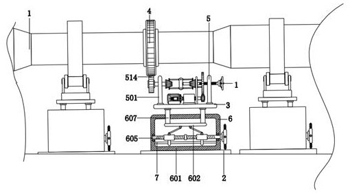
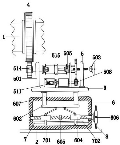
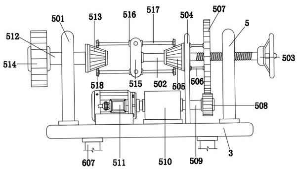
[0033]An inclined cement rotary kiln driving device, comprising a rotary kiln main body 1, a base 2 is provided under the rotary kiln main body 1, a support plate 3 is provided on the upper surface of the base 2, and the outer wall of the rotary kiln main body 1 is fixedly socketed with The toothed disc 4 is provided with a drive mechanism 5 below the toothed disc 4, and the drive mechanism 5 includes a vertical plate 501, a screw rod 502, a knob 503, a vertical plate 504, a first tapered tooth post 505, a short rod 506, a first gear 507, The second gear 508, the rotating rod 509, the reducer 510, the motor 511, the round bar 512, the second conical tooth column 513, the third gear 514, the I-shaped plate 515, the sleeve 516, the cross bar 517 and the third conical The tooth column 518 and the two vertical plates 501 are respectively located at the left and right ends of the upper surface of the supporting plate 3, the bottom of the vertical plate 501 is fixedly connected with ...
Embodiment 2
[0035] As an option, see Figure 1-4 , tilting cement rotary kiln driving equipment, the base plate 2 is connected with the supporting plate 3 through the connecting mechanism 6, and the connecting mechanism 6 includes a box body 601, a square plate 602, an inclined rod 603, a horizontal cylinder 604, a screw rod 605, and a turntable 606 And struts 607, the lower surface of the box body 601 is fixedly connected with the upper surface of the base 2, the left and right sides of the upper surface of the box body 601 are inserted with struts 607, the contact surface gap between the outer wall of the struts 607 and the box body 601 Cooperate, the top of support rod 607 is fixedly connected with the lower surface of supporting plate 3, and the bottom end of support plate 607 is fixedly connected with square plate 602, and the left and right sides of the lower surface of square plate 602 are all hinged with oblique rod 603, and the oblique rod 603 The bottom end is hinged with a hori...
Embodiment 3
[0038] As an option, see figure 2 with 4 , inclined cement rotary kiln drive equipment, the bottom end of the outer wall of the horizontal cylinder 604 is provided with an auxiliary mechanism 7, the auxiliary mechanism 7 includes a convex plate 701 and a sliding rod 702, and the two convex plates 701 are respectively fixed on the outer walls of the two horizontal cylinders 604 At the bottom end, the sliding rod 702 is laterally fixed below the inside of the box body 601 , and the outer wall of the sliding rod 702 is in clearance fit with the inner wall of the horizontal cylinder 604 .
[0039] The solution in this embodiment can be selectively used in combination with the solutions in other embodiments.
[0040] Working principle of the present invention:
[0041] When the tilting cement rotary kiln drive equipment needs to drive the main body 1 of the rotary kiln during use, the operator electrifies the motor 511, and after the motor 511 is electrified, the rotary rod 509,...
PUM
 Abstract
Description
Claims
Application Information
 - R&D
- Intellectual Property
- Life Sciences
- Materials
- Tech Scout
- Unparalleled Data Quality
- Higher Quality Content
- 60% Fewer Hallucinations
Browse by: Latest US Patents, China's latest patents, Technical Efficacy Thesaurus, Application Domain, Technology Topic, Popular Technical Reports.
© 2025 PatSnap. All rights reserved.Legal|Privacy policy|Modern Slavery Act Transparency Statement|Sitemap|About US| Contact US: help@patsnap.com


