
Non-contact torsional vibration measurement method based on machine vision

A non-contact, machine vision technology, applied in the direction of measuring devices, measuring ultrasonic/sonic/infrasonic waves, instruments, etc., can solve the problems of complex and expensive non-contact measuring devices, high application cost, single measuring point, etc.

Active Publication Date: 2020-10-30
感知矩阵(沈阳)科技有限公司
View PDF10 Cites 3 Cited by
  • Summary
  • Abstract
  • Description
  • Claims
  • Application Information

AI Technical Summary

Problems solved by technology

However, the above dedicated non-contact measuring devices are too complicated and expensive, making the application cost higher
In addition, another disadvantage of the above two methods is that the measurement point is single
Although the principle of torsional vibration measurement based on CCD camera technology has been invented in the past, such as Xu Minqiang proposed to use CCD camera technology to measure the torsional vibration of steam turbines, but the inventive method still needs to paste a paper tape with a pattern on the shafting of the steam turbine

Method used


Image

  • Non-contact torsional vibration measurement method based on machine vision
  • Non-contact torsional vibration measurement method based on machine vision
  • Non-contact torsional vibration measurement method based on machine vision

Examples


Embodiment

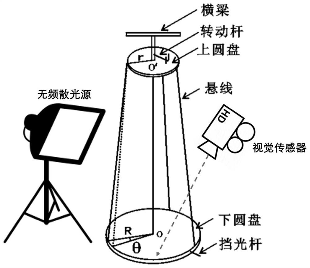
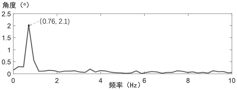
[0056] figure 2 It is the three-wire pendulum test scene diagram in the embodiment of the present invention, the main test object is a standard three-wire pendulum, and the turntable is the three-wire pendulum experimental standard turntable. The purpose of using this experimental sample is to verify the accuracy of the measurement method proposed by the present invention. The parameters of the three-wire pendulum are shown in Table 1. It can be seen that the test device of the present invention is much simpler than the traditional sensor device, and does not need expensive data acquisition equipment, acceleration sensors, laser vibrometers and the like. When the rotation angle of the turntable is less than 5°, the small displacement assumption of the present invention is met. Firstly, the three-wire pendulum was excited with a small rotation angle, and the torsional vibration of the turntable was recorded by the method, and the time was about 10 seconds. After micro-motion...


PUM


Abstract

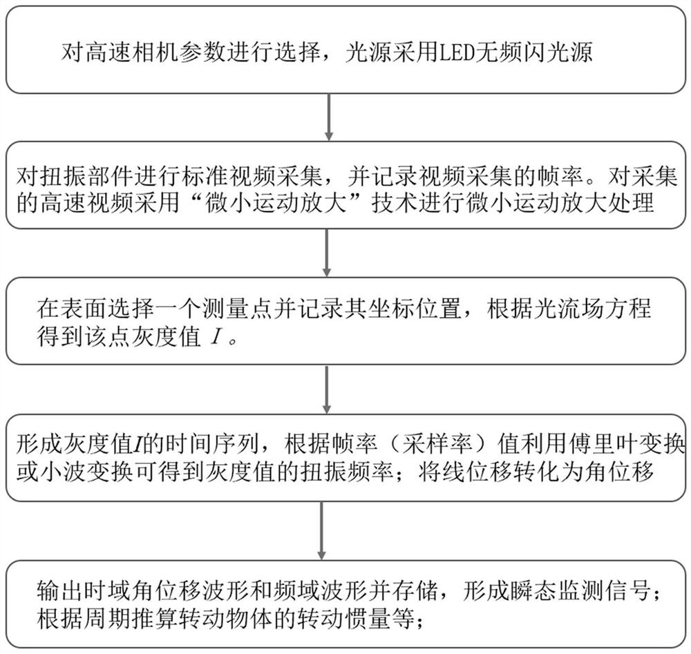
The invention provides a non-contact torsional vibration measurement method based on machine vision. The method comprises the steps of performing high-speed video acquisition on a torsional vibrationobject by using a computer vision technology, realizing separation, extraction and amplification of torsional vibration signals by using a 'micro motion amplification 'principle, and calculating the instantaneous frequency of the torsional vibration signals by using Fourier transform, wavelet transform and other technologies. According to the method provided by the invention, the torsional vibration time domain signals can be accurately extracted, and the torsional vibration frequency and period can be obtained. And the method is still effective to a tiny torsional vibration system. The methodhas the characteristics of being non-contact, high in test efficiency and only short in video acquisition time. Only a camera and lighting equipment are needed, a sensor and a data acquisition systemare not needed, mark points do not need to be pasted on the surface of the torsional vibration object, and accuracy and reliability are good. According to the method provided by the invention, the state of the shaft system of a rotary machine can be monitored. For a turntable system or a slender structure, the rotational inertia of the system, the shear modulus of the material and the like can becalculated.

Description

technical field [0001] The invention belongs to the technical field of non-contact measurement, in particular to a non-contact torsional vibration measurement method based on machine vision. Background technique [0002] Torsional vibration is one of the basic vibration forms of shafting, discs and other objects. During the rotation of the shafting system, fast and sometimes slow shafting torsional vibration cannot be avoided. Excessive torsional vibration will cause excessive vibration and noise of the transmission system. Therefore, the measurement of torsional vibration is one of the important contents of mechanical system detection. At present, most of the mechanical vibration sensors (acceleration sensors, laser vibrometers) are suitable for linear vibration, but not for torsional vibration measurement. At present, there are two types of torsional vibration measurement commonly used in engineering: one is contact measurement, for example, a resistive strain gauge is pa...

Claims


Application Information

Patent Timeline
IPC IPC(8): G01H9/00
CPCG01H9/00
Inventor 杨天智金洋陈立群
Owner 感知矩阵(沈阳)科技有限公司
Learn More