Cyclic shear test device under constant normal stiffness condition and application method thereof

A technology of normal stiffness and shear test, which is applied in the direction of testing material strength, measuring device, strength characteristics, etc. by applying stable shear force, which can solve the problems of inability to consider complex confining pressure conditions and inability to simulate well

Pending Publication Date: 2020-10-30
FUZHOU UNIV
View PDF0 Cites 6 Cited by
  • Summary
  • Abstract
  • Description
  • Claims
  • Application Information

AI Technical Summary

Problems solved by technology

[0004] Since the rock mass in underground engineering and the rock mass under the anchorage condition are under the boundary condition of constant normal stiffness, the traditional cyclic shear testing machine can only achieve constant normal load, and cannot consider the influence of complex confining pressure conditions, so it cannot perform well Simulate such engineering situations

Method used


Image

  • Cyclic shear test device under constant normal stiffness condition and application method thereof
  • Cyclic shear test device under constant normal stiffness condition and application method thereof
  • Cyclic shear test device under constant normal stiffness condition and application method thereof

Examples


Embodiment

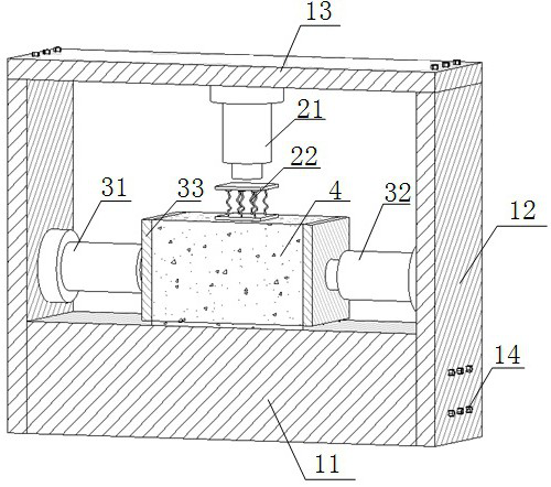
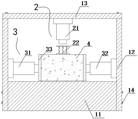
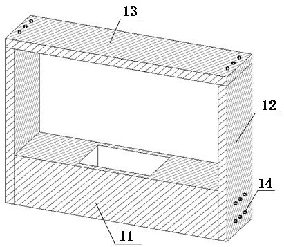
[0023] Example: such as Figure 1~8 As shown, a cyclic shear test device under constant normal stiffness conditions is provided, including a reaction force frame system 1, a shear force application system 3, a normal loading system 2 and an anchored fractured rock mass specimen 4;

[0024] The shear force application system 3 includes loading pads 33 located on both sides of the anchored fractured rock mass specimen, shearing hydraulic cylinders located on the sides of the loading pads, and hydraulic oil for supplying the two shearing hydraulic cylinders. The shearing force servo oil source; the shearing hydraulic cylinder is fixed inside the square loading plate.

[0025] The normal loading system 2 includes a normal hydraulic cylinder 21, an axial pressure servo oil source and a spring backing plate 22 for supplying oil to the found hydraulic cylinder, the normal hydraulic cylinder is located above the spring backing plate, and the spring The backing plate is located above ...


PUM


Abstract

The invention provides a cyclic shear test device under a constant normal stiffness condition. The cyclic shear test device comprises a counter-force frame system, a shear force applying system, a normal loading system and an anchored fractured rock mass test piece. The shearing force applying system, the normal loading system and the anchored fractured rock mass test piece are all located in thecounter-force frame system. The shear force applying system comprises loading cushion blocks located on the two sides of the anchored fractured rock mass test piece, shear hydraulic oil cylinders located on the side portions of the loading cushion blocks and a shear force servo oil source. The normal loading system comprises a normal hydraulic oil cylinder, an axial pressure servo oil source and aspring base plate, the normal hydraulic oil cylinder is located above the spring base plate, and the spring base plate is located above the anchored fractured rock mass test piece. The device is reasonable in design, simple in structure, easy and efficient to use and convenient to operate, the influence of the cyclic shear load on the shear characteristics of the anchored jointed rock mass underthe condition of constant normal rigidity can be clearly researched, scientific and reasonable anchoring design can be conducted, and the risk of engineering geological disasters is reduced.

Description

technical field [0001] The invention relates to a cyclic shear test device under the condition of constant normal stiffness and an application method thereof. Background technique [0002] Extensive cracks and joints in rock mass are the root cause of many landslides and collapses. In geotechnical engineering, cyclic shear loads generated by engineering activities such as underground blasting, vibration, and excavation loading and unloading may cause structural surface instability and damage. In addition, seismic activities are very active in some areas of my country, and many slopes, tunnels, water Hydropower and other projects are inevitably built in earthquake areas, and the closure and slippage of structural surfaces under the action of seismic cyclic loads and dynamic loads is an important reason for the failure of ground and underground projects. Anchor rods and anchor cables are widely used in rock mass engineering for the stability of jointed rock mass. The character...

Claims


Application Information

Patent Timeline
Patent Type & Authority Applications(China)
IPC IPC(8): G01N3/24G01N3/36G01N3/04
CPCG01N3/04G01N3/24G01N3/36G01N2203/0025G01N2203/0026G01N2203/0048
Inventor 吴学震蒋宇静周元锦王刚
Owner FUZHOU UNIV
Why Eureka
Try Eureka