Double-layer comb tooth driving MEMS scanning mirror for laser radar and preparation method

A laser radar, scanning mirror technology, applied in the field of micro-electromechanical, can solve the problems of high driving voltage, small scanning frequency and torsion angle, etc.

Active Publication Date: 2020-10-30
HEFEI UNIV OF TECH
View PDF11 Cites 9 Cited by
  • Summary
  • Abstract
  • Description
  • Claims
  • Application Information

AI Technical Summary

Problems solved by technology

[0005] Aiming at the shortcomings of existing MEMS scanning mirrors used for laser radar, the present invention provides a double-layer comb-driven MEMS scanning mirror for lase...

Method used


Image

  • Double-layer comb tooth driving MEMS scanning mirror for laser radar and preparation method
  • Double-layer comb tooth driving MEMS scanning mirror for laser radar and preparation method
  • Double-layer comb tooth driving MEMS scanning mirror for laser radar and preparation method

Examples


Embodiment 1

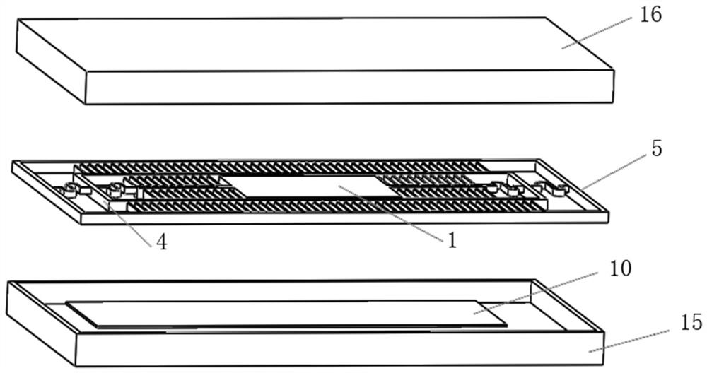
[0063] See Figure 1~2 , a double-layer comb-driven MEMS scanning mirror for lidar, including a transparent glass cap 16, a rotating scanning mirror body and a silicon substrate 15;

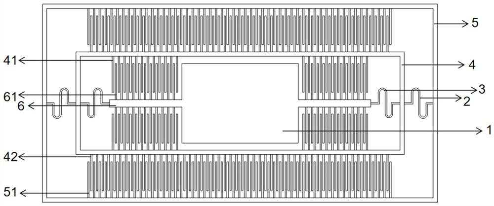
[0064] The body of the rotating scanning mirror is a square structural layer silicon material, and includes a square micromirror 1, a first S-shaped torsion beam 2, a second S-shaped torsion beam 3, a rectangular inner frame 4 and a rectangular outer frame 5;

[0065] The outer frame 5 is coaxially sleeved outside the inner frame 4, and the two ends of the inner frame 4 are respectively connected to the outer frame 5 through the first S-shaped torsion beam 2;

[0066] Both ends of the micromirror 1 are connected to the inner frame 4 through the straight connecting beam 6 and the second S-shaped torsion beam 3, so that the micromirror 1 is movably installed in the middle of the inner frame 4;

[0067] The center of the outer frame 5 is the origin, the length direction of the outer frame 5 is the...

Embodiment 2

[0087] The present invention also includes a method for preparing a double-layer comb-driven MEMS scanning mirror for laser radar, which adopts bulk silicon processing technology and includes the following steps:

[0088] Step (1): Take a double-throw SOI wafer, and include a top silicon layer 100, a middle silicon oxide layer 101, and a bottom silicon layer 102. The layer structure of the double-throw SOI wafer is as follows Figure 7 shown;

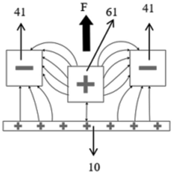
[0089]Deep reactive ion etching is used on the top silicon layer 100 to expose the micromirror 1, the direct connecting beam 6, the first S-shaped torsion beam 2, the second S-shaped torsion beam 3, the inner frame 4, the outer frame 5, Drive combs 61, inner movable combs 41, outer movable combs 42 and fixed combs 51; drive combs 61 and inner movable combs 41 are arranged alternately, outer movable combs 42 and The fixed comb teeth 51 are alternately arranged; as Figure 8 shown.

[0090] Step (2): On the basis of step 1, use a mask ...


PUM

PropertyMeasurementUnit
Thicknessaaaaaaaaaa
Thicknessaaaaaaaaaa
Thicknessaaaaaaaaaa

Abstract

The invention relates to the technical field of micro electro mechanical systems, in particular to a double-layer comb tooth driving MEMS scanning mirror for a laser radar and a preparation method. The MEMS scanning mirror comprises a transparent glass cap, a rotary scanning mirror body and a silicon substrate. The rotary scanning mirror body comprises a square micro mirror, a first S-shaped torsion beam, a second S-shaped torsion beam, a rectangular inner-layer frame and a rectangular outer-layer frame; the outer-layer frame is coaxially arranged outside the inner-layer frame in a sleeving mode, and the two ends of the inner-layer frame are connected with the outer-layer frame through first S-shaped torsion beams respectively; the two ends of the micro mirror are correspondingly connectedwith the inner-layer frame through a straight connecting beam and a second S-shaped torsion beam in sequence, so that the micro mirror is movably mounted in the middle of the inner-layer frame; and driving voltage is applied to the comb tooth electrode layer, the upper electrode and the lower electrode, so that the micro mirror can rotate in the movable cavity. According to the preparation method, the bulk silicon processing technology and the SOI-based silicon-glass bonding technology are adopted to complete manufacturing and packaging of the MEMS scanning mirror, the processing efficiency is high, and the repeatability is high.

Description

technical field [0001] The invention relates to the field of micro-electromechanical technology, in particular to a double-layer comb-driven MEMS scanning mirror for laser radar and a preparation method. Background technique [0002] With the continuous development of various advanced devices, lidar is gradually developing towards low cost, low power consumption, miniaturization and convenient application. In particular, the development of MEMS technology has driven the development of MEMS scanning mirrors. The MEMS scanning mirror used in the lidar system requires a large scanning angle, low driving voltage, effectively reducing the power consumption of the system, and the process is simple and easy to integrate. [0003] MEMS scanning mirrors mainly rely on micro-actuators to drive the movable mirror to produce rotation or translation, thereby changing the propagation direction of incident light. MEMS scanning mirrors can be divided into four types according to their driv...

Claims


Application Information

Patent Timeline
IPC IPC(8): G01S7/481G02B26/10G02B26/08B81B7/02
CPCG01S7/4817G02B26/10G02B26/0841B81B7/02Y02A90/10
Inventor 许高斌杜林云花翔马渊明陈兴于永强
Owner HEFEI UNIV OF TECH
Why Eureka
Try Eureka