Swing-type friction nano-generator and energy harvester

A nanogenerator and swing friction technology, applied in the direction of friction generators, electrical components, electromechanical devices, etc., can solve the problems of low energy collection efficiency, achieve the effect of improved energy collection efficiency, low loss, and wide application prospects

Active Publication Date: 2020-10-30
BEIJING INST OF NANOENERGY & NANOSYST
View PDF7 Cites 10 Cited by
  • Summary
  • Abstract
  • Description
  • Claims
  • Application Information

AI Technical Summary

Problems solved by technology

[0006] However, there are still many deficiencies in the existing energy harvesters based on triboelectric nanogenerators, such as: 1. The energy harvesting efficiency is very low under low frequency operation, which needs to be further improved; 2. Most of the energy harvesting process is in one-dimensional direction, such as based on friction The wind energy harvester of the nanogenerator, the vibrating membrane in the middle is in contact with the upper and lower friction layers to generate electricity under the action of wind force, it can only respond to the wind blowing in one direction to obtain energy conversion, and it has limitations in multi-dimensional space

Method used


Image

  • Swing-type friction nano-generator and energy harvester
  • Swing-type friction nano-generator and energy harvester
  • Swing-type friction nano-generator and energy harvester

Examples


no. 1 example

[0066] In a first exemplary embodiment of the present disclosure, a pendulum type triboelectric nanogenerator is provided.

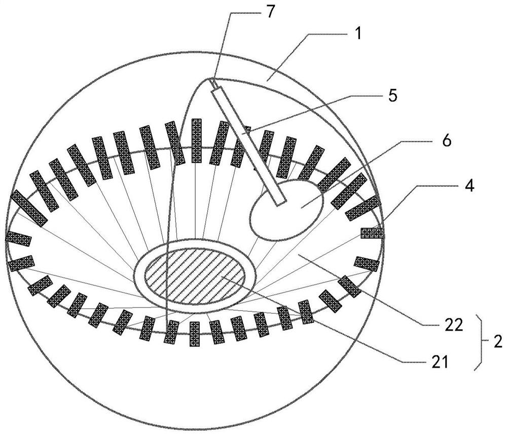
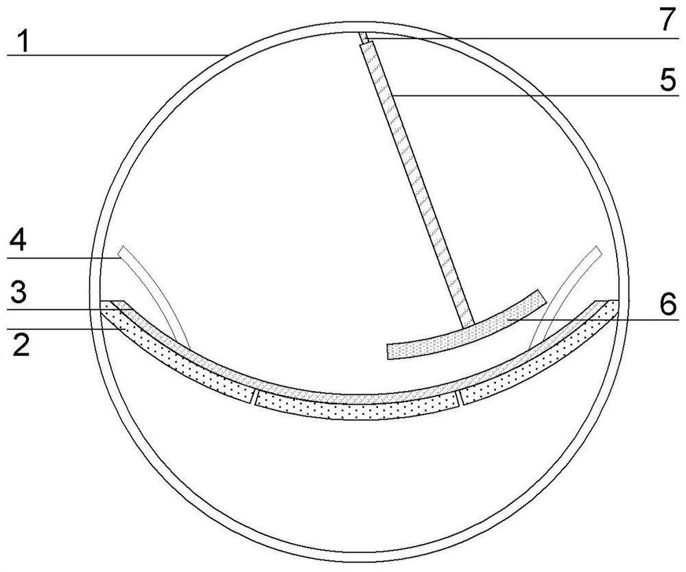
[0067] figure 1 It is a schematic structural diagram of the pendulum friction nanogenerator according to the first embodiment of the present disclosure. Among them, in order to highlight the structure of the arc-shaped double-electrode layer 2, the dielectric layer 3 covering the upper surface of the arc-shaped double-electrode layer 2 is not shown. In this embodiment, the first distributed friction layer 4 is located on the dielectric layer 3. The upper surface of layer 3, since the dielectric layer 3 is not shown, therefore figure 1 In the diagram, the first distributed friction layer 4 is located above the arc-shaped double-electrode layer 2 for illustration. figure 2 For such figure 1 A schematic cross-sectional view of the pendulum-type triboelectric nanogenerator cut from half of the arc-shaped double-electrode layer.

[0068] to combine figu...

no. 2 example

[0090] In a second exemplary embodiment of the present disclosure, a pendulum type triboelectric nanogenerator is provided.

[0091] The pendulum friction nanogenerator in this embodiment is further improved on the basis of the structure of the first embodiment. In this embodiment, the pendulum friction nanogenerator combines friction power generation and electromagnetic power generation Enables energy harvesting.

[0092] Figure 8 It is a schematic structural diagram of a pendulum friction nanogenerator according to the second embodiment of the present disclosure.

[0093] refer to Figure 8 As shown, in the pendulum friction nanogenerator of this embodiment, other structures are the same as those of the first embodiment, the difference is that a magnet is arranged on the side of the first freely swinging friction layer 6 away from the first distributed friction layer 4 8. A coil 9 is arranged on the inner surface of the corresponding housing. The magnet 8 and the first f...

no. 3 example

[0099] In a third exemplary embodiment of the present disclosure, a pendulum type triboelectric nanogenerator is provided.

[0100] The pendulum type friction nanogenerator of the present disclosure includes: a shell, which is a closed shell structure, with a cavity inside; a swing structure, located in the cavity, including: a swing rod; and a freely swinging friction layer, which is connected to the pendulum the end of the rod is rigidly connected; the electrode layer, located on the inner surface of the housing, includes a first electrode layer and a second electrode layer spaced apart; and a distributed friction layer, located within a range capable of contacting the oscillating structure during the oscillating process, The materials of the friction layer and the freely swinging friction layer are in a different triboelectric sequence, one end is fixed on the electrode layer (the first electrode layer or the second electrode layer), and the other end is a free end. Wherein...


PUM


Abstract

The invention relates to a swing-type friction nano-generator and an energy harvester. The swing-type friction nano-generator comprises a housing, a swing structure, an electrode layer and a distributed friction layer, wherein the housing is of a closed housing structure and is internally provided with a cavity; the swing structure is positioned in the cavity and comprises a swing rod and a free swing friction layer which is rigidly connected with the tail end of the swing rod; the electrode layer is located on an inner surface of the housing and comprises a first electrode layer and a secondelectrode layer which are spaced apart from each other; the material of the distributed friction layer and the material of the free swing friction layer are located in different triboelectric sequences, one end of the distribution friction layer is fixed on the electrode layer, and the other end is a free end; and when the swing structure swings in the housing due to external excitation, the freeswing friction layer of the swing structure swings along with the swing structure, and electrical output is correspondingly generated on the electrode layer through friction electrification between the free swing friction layer of the swing structure and the distributed friction layer. The swing-type friction nano-generator has high energy collection efficiency, can adapt to various environments,has high stability and reliability, can respond to external excitation at any angle, and has a wide application prospect.

Description

technical field [0001] The disclosure belongs to the technical field of energy collection, and relates to a pendulum friction nanometer generator and an energy harvester. Background technique [0002] With the rapid development of the Internet and micro-nano electronic devices, the world is facing serious problems such as excessive energy consumption and energy shortages. Finding sustainable energy has become an urgent need for the future development of the Internet of Everything, especially in every corner of the world. It will become a huge project and require a huge amount of energy to supply power to these hundreds of millions of distributed electronic devices. [0003] Existing traditional energy sources such as lithium batteries not only have a short lifespan and cannot be replaced continuously, but maintaining a huge amount of batteries requires a lot of manpower and material resources. In addition, traditional batteries have potential environmental pollution; at the...

Claims


Application Information

Patent Timeline
Patent Type & Authority Applications(China)
IPC IPC(8): H02N1/04H02K35/02
CPCH02N1/04H02K35/02
Inventor 林志明其他发明人请求不公开姓名
Owner BEIJING INST OF NANOENERGY & NANOSYST
Why Eureka
Try Eureka