Microbial grouting anchoring method for grouting in cavity and microbial grouting anchoring structure

An anchoring method and microbial technology, applied in the direction of building structure, building components, heat preservation, etc., can solve the problems affecting the compactness of the product, the air is not easy to discharge, and the anchoring effect is poor, so as to improve the uniformity of the product, good filling, The effect of preventing clogging

Active Publication Date: 2020-11-03
SHANDONG JIANZHU UNIV +2
View PDF6 Cites 3 Cited by
  • Summary
  • Abstract
  • Description
  • Claims
  • Application Information

AI Technical Summary

Problems solved by technology

However, the inventors have found that when microbial grouting anchors the screw, due to the low viscosity of several components of the grouting liquid, it is not easy to remain after being injected into the tunnel; after the mixing of several grouting components, calcium carbonate deposits are formed quickly, and the method of inserting the screw The anchoring effect of the method is poor; the air in the orifice grouting channel is not easy to discharge, which affects the compactness of the product

Method used


Image

  • Microbial grouting anchoring method for grouting in cavity and microbial grouting anchoring structure
  • Microbial grouting anchoring method for grouting in cavity and microbial grouting anchoring structure
  • Microbial grouting anchoring method for grouting in cavity and microbial grouting anchoring structure

Examples


Embodiment 1

[0045] In a typical embodiment of the present invention, such as Figure 1-Figure 7 As shown, a microbial grouting anchoring method for cavity grouting is proposed.

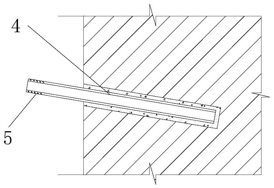
[0046] First, the anchor member used in this method is composed of a hollow anchor rod (in this embodiment, a hollow screw 4) and a nut 17. The anchor section of the hollow screw 4 extends into the borehole of the anchor matrix 1, and the hollow screw 4 The free section is provided with a threaded button 5 and is tightly connected with a nut 17 .

[0047] The steps of its anchoring method are:

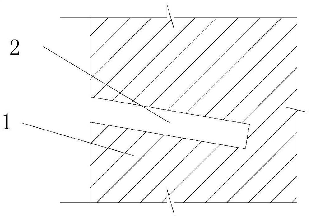
[0048] Step 1, first drill holes on the anchorage substrate 1 such as the wall, such as figure 1 Shown; the diameter of the borehole 2 is 2 to 3mm larger than the hollow screw of the anchoring member, so as to fill the screw.

[0049] The borehole is inclined downward, and the angle with the horizontal direction is about 15-20 degrees. The height of the borehole opening is higher than the height of the borehole bottom ...

Embodiment 2

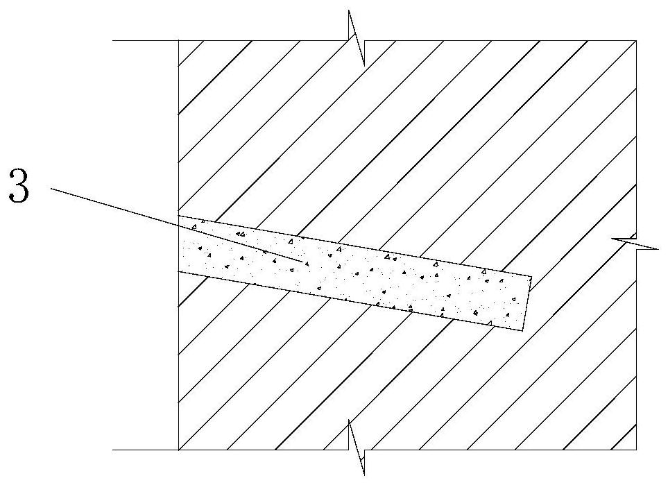
[0078] This embodiment provides a microbial grouting anchorage structure, such as Figure 6 As shown, it includes a hollow anchor rod (here it is a hollow screw 4), the hollow anchor rod is a hollow structure, the middle part of the hollow anchor rod is provided with a side hole communicating with the internal cavity, and the hollow screw rod 4 extends to the drill hole 2 of the anchor matrix 1 A calcium carbonate cement body 18 induced by microorganisms is arranged between the borehole and the hollow screw 4, and a fixed object 16 is arranged on the side wall of the anchoring matrix. 19 and nut 17, the first surface of the wedge-shaped backing plate is attached to the fixed object, the second surface of the wedge-shaped backing plate is adjacent to the nut, the second surface of the wedge-shaped backing plate is perpendicular to the axial direction of the hollow screw rod 4, and the The end face is pressed tightly against the second face of the wedge-shaped backing plate.

...


PUM

PropertyMeasurementUnit
diameteraaaaaaaaaa

Abstract

The invention discloses a microbial grouting anchoring method for grouting in a cavity and a microbial grouting anchoring structure. The method comprises the following steps that an anchoring base body is drilled, multiple sets of grouting pipes are installed in a cavity of a hollow anchoring rod, part of the grouting pipes extend to the bottom of the cavity, part of the grouting pipes extend outof the hollow anchoring rod from a side hole in the middle of the hollow anchoring rod, and the hollow anchoring rod is inserted into a drilled hole; grouting liquid is injected into the drilled holethrough the grouting pipes; and a fixed object is installed at the side wall of the anchoring base body, a nut is installed on the hollow anchoring rod, and anchoring is completed.

Description

technical field [0001] The invention belongs to the technical field of grouting and anchoring, and in particular relates to a microbial grouting and anchoring method and an anchoring structure for grouting in a cavity. Background technique [0002] The statements herein merely provide background information related to the present invention and do not necessarily constitute prior art. [0003] Anchor bolts are mechanical fasteners consisting of anchor rods, nuts and backing plates. The anchor rod needs to be anchored into the base of the wall to a certain depth, and then the wall insulation or decorative materials are fixed through the nut. The materials used for cementing anchor bolts mainly include cement-based and epoxy resin. Cement-based materials are not effective when the anchoring depth is large due to the volume shrinkage of cement hardening, the material is prone to water, and poor fluidity; epoxy resin materials are easy to age and have certain toxicity. The cal...

Claims


Application Information

Patent Timeline
Patent Type & Authority Applications(China)
IPC IPC(8): E04B1/38E04B1/76E04F13/08
CPCE04B1/38E04B1/7629E04F13/0801
Inventor 贾强张鑫赵庆瑞盛乾
Owner SHANDONG JIANZHU UNIV
Why Eureka
Try Eureka