
Pulse plasma thruster

A pulsed plasma and thruster technology, applied in the aerospace field, can solve problems such as poor controllability, low energy utilization rate, and low discharge stability, and achieve high ionization rate, high density, and high energy deposition efficiency.

Active Publication Date: 2020-11-03
XI AN JIAOTONG UNIV
View PDF23 Cites 2 Cited by
  • Summary
  • Abstract
  • Description
  • Claims
  • Application Information

AI Technical Summary

Problems solved by technology

However, the traditional plasma thruster based on pulse discharge mainly uses thermal plasma ablation propellant to generate thrust, which has low energy utilization rate, low discharge stability, and poor controllability, which seriously restricts the application of plasma in the aerospace field. application

Method used


Image

  • Pulse plasma thruster

Examples


Embodiment Construction

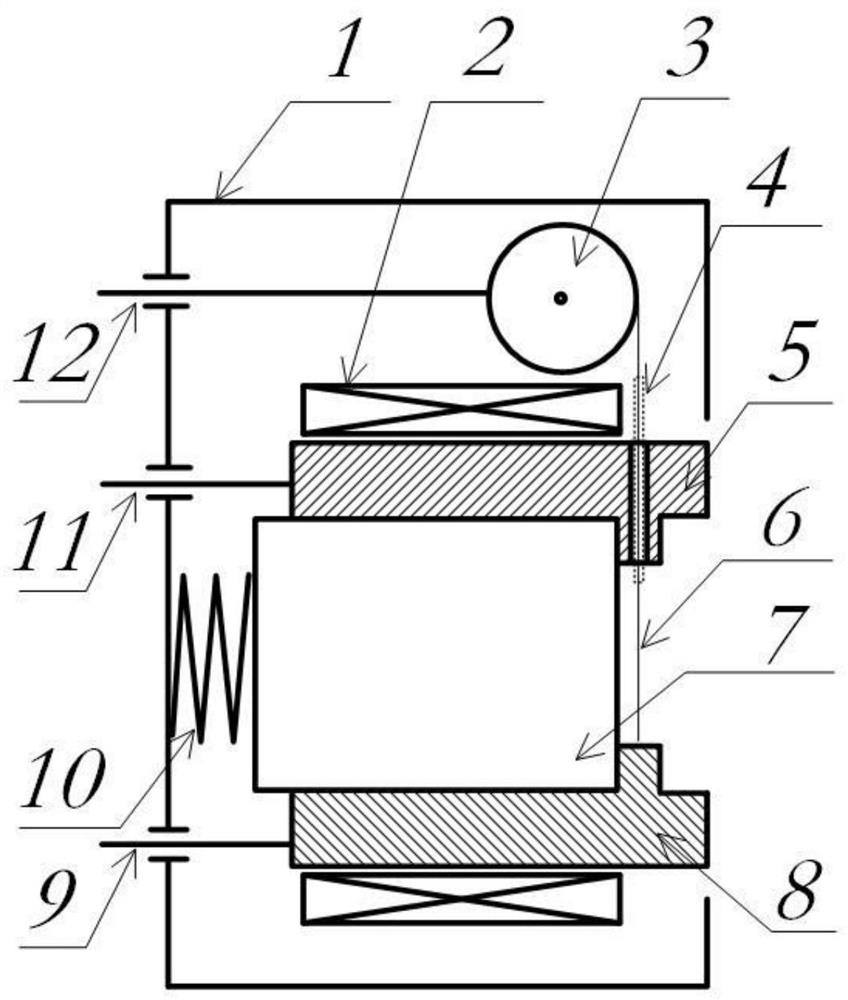
[0025] The following will refer to the attached figure 1 Specific examples of the present invention are described in more detail. Although specific embodiments of the invention are shown in the drawings, it should be understood that the invention may be embodied in various forms and is not limited to the embodiments set forth herein. Rather, these embodiments are provided for more thorough understanding of the present invention and to fully convey the scope of the present invention to those skilled in the art.

[0026] It should be noted that certain terms are used in the specification and claims to refer to specific components. Those skilled in the art should understand that they may use different terms to refer to the same component. The specification and claims do not use differences in nouns as a way of distinguishing components, but use differences in functions of components as a criterion for distinguishing. "Includes" or "comprises" mentioned throughout the specifica...


PUM

PropertyMeasurementUnit
lengthaaaaaaaaaa

Abstract

The invention relates to a pulse plasma thruster. In the pulse plasma thruster, an internal cavity isolated from a vacuum environment is formed in a shell, an anode is fixed to the shell, the anode isconnected to the positive electrode of a pulse power supply through an anode connecting wire, the anode is provided with a through hole facing a cathode, and the cathode is fixed to the shell; and the cathode is connected to the negative electrode of the pulse power supply through a cathode connecting wire, a metal wire penetrates through the through hole and abuts against the cathode, the anode,the metal wire and the cathode are exposed in the vacuum environment, and in response to a pulse signal, the metal wire loads pulse current to electrically explode to form plasma.

Description

technical field [0001] The invention belongs to the field of aerospace technology, in particular to a pulse plasma thruster. Background technique [0002] In the field of aerospace, plasma-based electric propulsion technology is the only way for space navigation. However, the traditional plasma thruster based on pulse discharge mainly uses thermal plasma ablation propellant to generate thrust, which has low energy utilization rate, low discharge stability, and poor controllability, which seriously restricts the application of plasma in the aerospace field. application. [0003] The above information disclosed in this Background section is only for enhancement of understanding of the background of the invention and therefore it may contain information that does not form the prior art that is already known in this country to a person of ordinary skill in the art. Contents of the invention [0004] Aiming at the problems existing in the prior art, the present invention prop...

Claims


Application Information

Patent Timeline
Patent Type & Authority Applications(China)
IPC IPC(8): F03H1/00
CPCF03H1/0087
Inventor 王亚楠韩若愚任林渊丁卫东欧阳吉庭
Owner XI AN JIAOTONG UNIV
Learn More