Device and method for measuring laser-damaged three-dimensional structure

A technology for measuring laser and three-dimensional, which is applied in measuring devices, optical testing of flaws/defects, material analysis through optical means, etc. It can solve the problem of time-consuming and labor-intensive detection, inability to detect depth information of damage, complex and expensive operation of detection equipment and other problems, to achieve the effect of increasing practicability, simple structure, and non-destructive measurement

Active Publication Date: 2020-11-03
JIANGNAN UNIV
View PDF13 Cites 3 Cited by
  • Summary
  • Abstract
  • Description
  • Claims
  • Application Information

AI Technical Summary

Problems solved by technology

However, these methods have more or less shortcomings, such as the need for destructive sampling analysis or drilling analysis, which cannot achieve non-destructive testing; or the detection equipment is complex and expensive, the operation is inconvenient, the detection is not time-effective, time-consuming and laborious, and the spatial resolution Low, unable to detect damage depth information, etc.

Method used


Image

  • Device and method for measuring laser-damaged three-dimensional structure
  • Device and method for measuring laser-damaged three-dimensional structure
  • Device and method for measuring laser-damaged three-dimensional structure

Examples


Embodiment 1

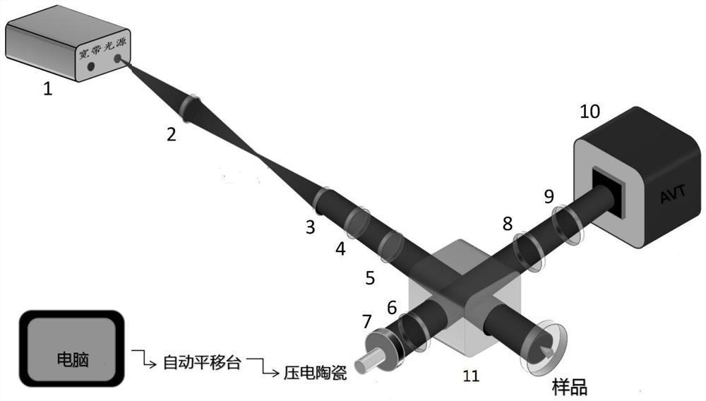
[0033] Such as figure 1 As shown, the device for realizing laser three-dimensional damage measurement based on phase-shift digital holography technology of the present invention includes a superluminescent light-emitting diode light source 1, a focusing lens 2, a collimating lens 3, an attenuation plate 4, a polarizer 5, and a beam-splitting prism 11. Quarter wave plate 6, reflecting mirror 7, imaging lens 8, analyzer 9, imaging device 10; Described superluminescent light-emitting diode light source 1 vertically places focusing lens 2 and collimating lens 3 along this laser beam direction, after that Attenuation sheet 4, polarizer 5 and beam splitting prism 11 are arranged in sequence; beam splitting prism 11 divides the light beam into reflected beam and transmitted beam, and a quarter wave plate 6, reflector 7, piezoelectric ceramics, electric Control the translation platform, and the electric control translation platform is connected with the computer. A polarizer 8, an im...

Embodiment 2

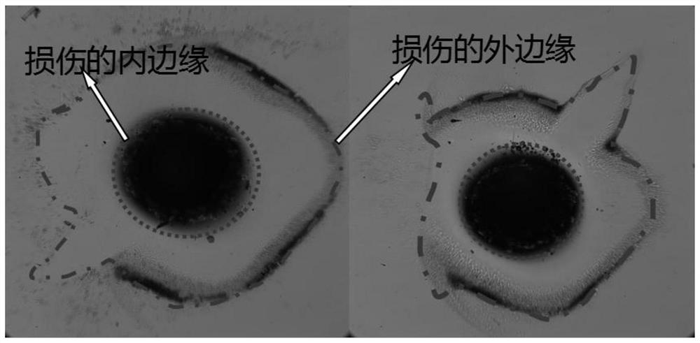
[0036]The three-dimensional laser damage is measured by using the phase-shift digital holography technology designed in Example 1. The damage size in the damaged sample used is about 2.5 mm, and the residual stress depth area is about 200-300 microns. Build the measuring device according to the mode of embodiment 1, because the focal length of imaging lens 8 is 8 centimeters, so in order to obtain a magnified clear image, need to be placed on the sample to be measured and the position of distance 13.5 centimeters from imaging lens 8, and from imaging lens The distance from 8 to the target surface of imaging device 10 is about 28.5 centimeters. The minimum pixel unit of the imaging device 10 is 7.4 microns, and its resolution is 2048×2048. When the distance between the imaging device and the imaging lens exceeds 0.5cm on the basis of 28.5cm, it will cause defocus and unclear imaging.

[0037] In the detection process, open the superluminescent light-emitting diode light source...


PUM


Abstract

The invention discloses a device and method for measuring a laser damage three-dimensional structure, and belongs to the field of phase shift digital holography. According to the invention, a corresponding phase shift amount is introduced according to a phase shift algorithm, and a corresponding hologram is recorded by CCD imaging equipment. Compared with other methods, the method is simple in structure and easy to operate, the cost of laser damage detection is reduced, rapid and nondestructive measurement of three-dimensional damage is achieved, and convenience is brought to damage repair.

Description

technical field [0001] The invention relates to a device and method for measuring a three-dimensional structure of laser damage, belonging to the field of phase-shift digital holography. Background technique [0002] With the continuous development of laser technology, the laser power becomes higher and higher. High-power laser devices such as ignition devices in the United States, laser megajoules in France, and Shenguang III in China are the most typical representatives. In these practical applications, the energy intensity of the transmitted light often reaches the maximum optical damage threshold of the optical element, and each optical element may be caused by the process in the manufacturing process, impurities in the glass material, the environment of use, or the conditions of excitation. And produce defects, these defects are prone to small-scale focusing under the irradiation of strong laser light, which will cause damage to the surface of the component and the film...

Claims


Application Information

Patent Timeline
Patent Type & Authority Applications(China)
IPC IPC(8): G01N21/23G01N21/95G01N21/17
CPCG01N21/17G01N21/23G01N21/95G01N2021/1785G01N2201/068
Inventor 刘诚齐乃杰王绶玙孔艳蒋志龙
Owner JIANGNAN UNIV
Why Eureka
Try Eureka