
Control circuit and control method for industrial camera system time sequence

A technology of industrial cameras and control circuits, which is applied in the direction of program control, program control, and electrical program control in sequence/logic controllers. Impact on lifespan, enhance control, and provide system stability effects

Active Publication Date: 2020-11-03
SUZHOU CASIA ALL PHASE INTELLIGENCE TECH CO LTD
View PDF9 Cites 0 Cited by
  • Summary
  • Abstract
  • Description
  • Claims
  • Application Information

AI Technical Summary

Problems solved by technology

[0007] The problem to be solved by the present invention is that in the timing control of industrial camera systems in the prior art, the existing timing control method has technical problems such as high requirements on hardware equipment, insufficient applicability, and certain difficulty in operation.

Method used


Image

  • Control circuit and control method for industrial camera system time sequence
  • Control circuit and control method for industrial camera system time sequence

Examples


Embodiment Construction

[0036] In the following, specific examples will be used to describe in detail and illustrate the technical solutions of the present invention.

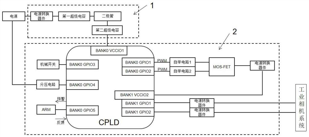
[0037] Such as figure 1 As shown, the control circuit schematic diagram of the industrial camera system timing is given. The control circuit includes an energy storage circuit 1 and a power-on sequence control circuit 2. The energy storage circuit 1 includes two sets of supercapacitors, namely the first supercapacitor and the second supercapacitor Two supercapacitors, a power conversion device is provided between the input terminal of the first supercapacitor and the input power supply, usually directly purchased power conversion modules (220V to 48V / 24V / 12V) or power adapters. Here, the number of supercapacitors in the first and second supercapacitors is 1, and the capacity is selected according to the overall power consumption of the system and the required application scenarios. A diode is connected in series between the first and ...


PUM


Abstract

The invention discloses a control circuit and a control method for a time sequence of an industrial camera system, and belongs to the technical field of high-speed industrial cameras. In a power-on time sequence process of the system, after power input, the power firstly passes through a super capacitor and then enters a CPLD, and a system switch is turned on for power conversion. According to thecontrol circuit and the control method, the traditional pure hardware power-on time sequence is replaced by combining the software logic control of the CPLD with the application of the super capacitor and the mechanical switch, and all chips needing the power-on time sequence and the power-off time sequence can be accurately achieved according to the requirements of specifications.

Description

technical field [0001] The invention belongs to the technical field of high-speed industrial cameras, and in particular relates to a control circuit and a control method for the timing of an industrial camera system. Background technique [0002] The application scenarios of industrial cameras have high requirements on the environment, such as large high and low temperature gaps, complex magnetic field changes, and severe vibrations, etc., will have a certain impact on the life of industrial cameras. Therefore, in order to ensure stable operation of industrial equipment and a longer service life , engineers face enormous challenges. Usually, once industrial equipment starts to work, it is required to continue to operate without failure. It should be noted that the industrial camera is only a vague name for the image capture and processing capabilities of the camera itself. Different from the usual high-speed industrial cameras in industrial applications, industrial cameras ...

Claims


Application Information

Patent Timeline
Patent Type & Authority Applications(China)
IPC IPC(8): H04N5/232G05B19/05
CPCG05B19/054H04N23/65
Inventor 主宾汪雪林余章卫
Owner SUZHOU CASIA ALL PHASE INTELLIGENCE TECH CO LTD
Learn More