Laser module and laser device
A laser module and laser technology, applied in the direction of lasers, laser components, semiconductor lasers, etc., can solve the problems of large-scale devices and increased manufacturing costs
- Summary
- Abstract
- Description
- Claims
- Application Information
AI Technical Summary
Problems solved by technology
Method used
Image

Examples
no. 1 approach
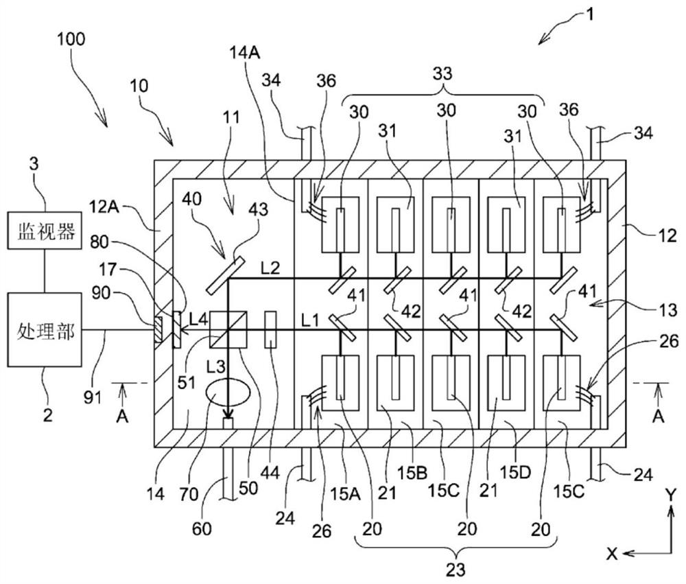
[0017] figure 1 It is a partial plan cross-sectional view schematically showing the laser device 100 in the first embodiment of the present invention. Such as figure 1 As shown, the laser device 100 includes a laser module 1 , a processing unit 2 connected to the laser module 1 , and a monitor 3 connected to the processing unit 2 .
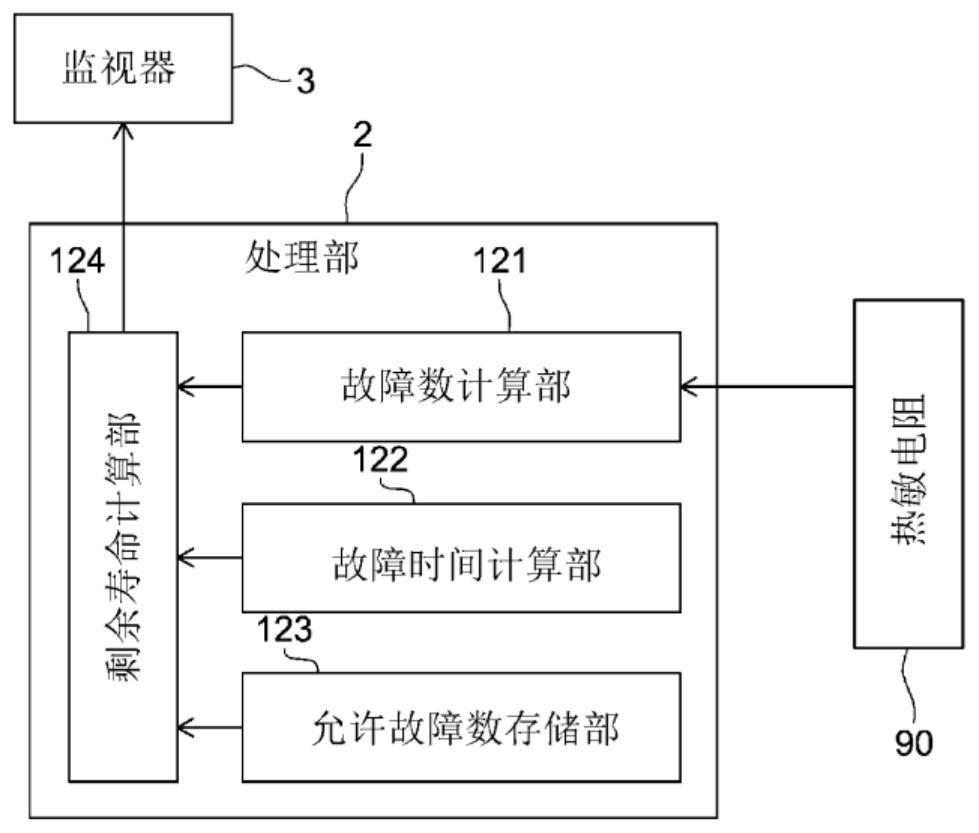
[0018] The laser module 1 of the laser device 100 outputs laser light from a plurality of laser elements to the outside, and detects a temperature change of the module through a thermistor. The processing unit 2 of the laser device 100 calculates the remaining lifetime of the laser module 1 based on the data from the thermistor. The monitor 3 of the laser device 100 displays the remaining life of the laser module 1 calculated by the processing unit 2 .
[0019] Such as figure 1 As shown, the laser module 1 is equipped with: a plurality of (five in this embodiment) laser elements 20, which emit laser light along the +Y direction; a plurality (f...
no. 2 approach
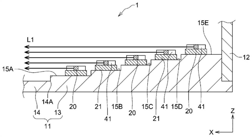
[0066] Next, the laser module 201 in the second embodiment of the present invention will be described. here, Figure 4 is a partial cross-sectional plan view schematically showing the laser module 201 . Such as Figure 4 As shown, the laser module 201 has an encapsulation case 210 . The packaging case 210 includes a bottom plate 211 and a frame body 212 fixed on the outer edge of the bottom plate 211 . The bottom plate 211 is formed in approximately half the size of the bottom plate 11 of the first embodiment, and has a base portion 214 and a stepped portion 213 . Five layers of mounting surfaces 215A to 215E are formed on the stepped portion 213 so as to gradually increase in height toward the −X direction, and the laser element 20 and the reflection mirror 41 are fixed to the mounting surfaces 215A to 215E, respectively. That is, the laser module 201 has only the first laser element group 23 unlike the laser module 1 in the first embodiment.
[0067] The laser light L1 ...
no. 3 approach
[0072] Next, the laser module 301 in the third embodiment of the present invention will be described. here, Figure 5 It is a partial plan cross-sectional view schematically showing the laser module 301 . Such as Figure 5 As shown, the laser module 301 has an encapsulation case 310 . The packaging case 310 includes a flat bottom plate 311 and a frame 312 fixed on the outer edge of the bottom plate 311 . Five laser elements 20 (that is, the above-mentioned first laser element group 23 ) are mounted on the bottom plate 311 via the base 21 . Further, five reflection mirrors 341 , a 1 / 2 wavelength plate 44 , a beam splitter 50 , and a condenser lens 70 are installed on the bottom plate 311 .
[0073] The five reflecting mirrors 341 are arranged to be displaced from each other at a predetermined pitch along the Y direction. In addition, the reflective mirror 341 located closest to the −X direction side is closest to the corresponding laser element, and the reflective mirror 3...
PUM
 Abstract
Description
Claims
Application Information
 - R&D Engineer
- R&D Manager
- IP Professional
- Industry Leading Data Capabilities
- Powerful AI technology
- Patent DNA Extraction
Browse by: Latest US Patents, China's latest patents, Technical Efficacy Thesaurus, Application Domain, Technology Topic.
© 2024 PatSnap. All rights reserved.Legal|Privacy policy|Modern Slavery Act Transparency Statement|Sitemap