Flow control structure of nitrogen-oxygen separation device

A flow control, nitrogen and oxygen separation technology, applied in the field of oxygen generators, can solve the problems of low work efficiency and high labor intensity

Active Publication Date: 2020-11-06
安徽康居人健康科技有限公司
View PDF11 Cites 1 Cited by
  • Summary
  • Abstract
  • Description
  • Claims
  • Application Information

AI Technical Summary

Problems solved by technology

[0005] The invention drives each flow limiting plate to move to limit the flow by driving the cylinder, and controls the communication between multiple air outlet pipes and the outlet pipes through the cooperation of the lifting motor and the rotating motor. The flow control structure is completely automatic, and in the process of flow control, The traditional flow control structure for nitrogen and oxygen separation requires manual assistance, high labor intensity and low work efficiency.

Method used


Image

  • Flow control structure of nitrogen-oxygen separation device
  • Flow control structure of nitrogen-oxygen separation device
  • Flow control structure of nitrogen-oxygen separation device

Examples


Embodiment Construction

[0033] The technical solutions of the present invention will be clearly and completely described below in conjunction with the embodiments. Apparently, the described embodiments are only some of the embodiments of the present invention, not all of them. Based on the embodiments of the present invention, all other embodiments obtained by persons of ordinary skill in the art without creative efforts fall within the protection scope of the present invention.

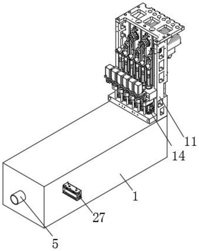
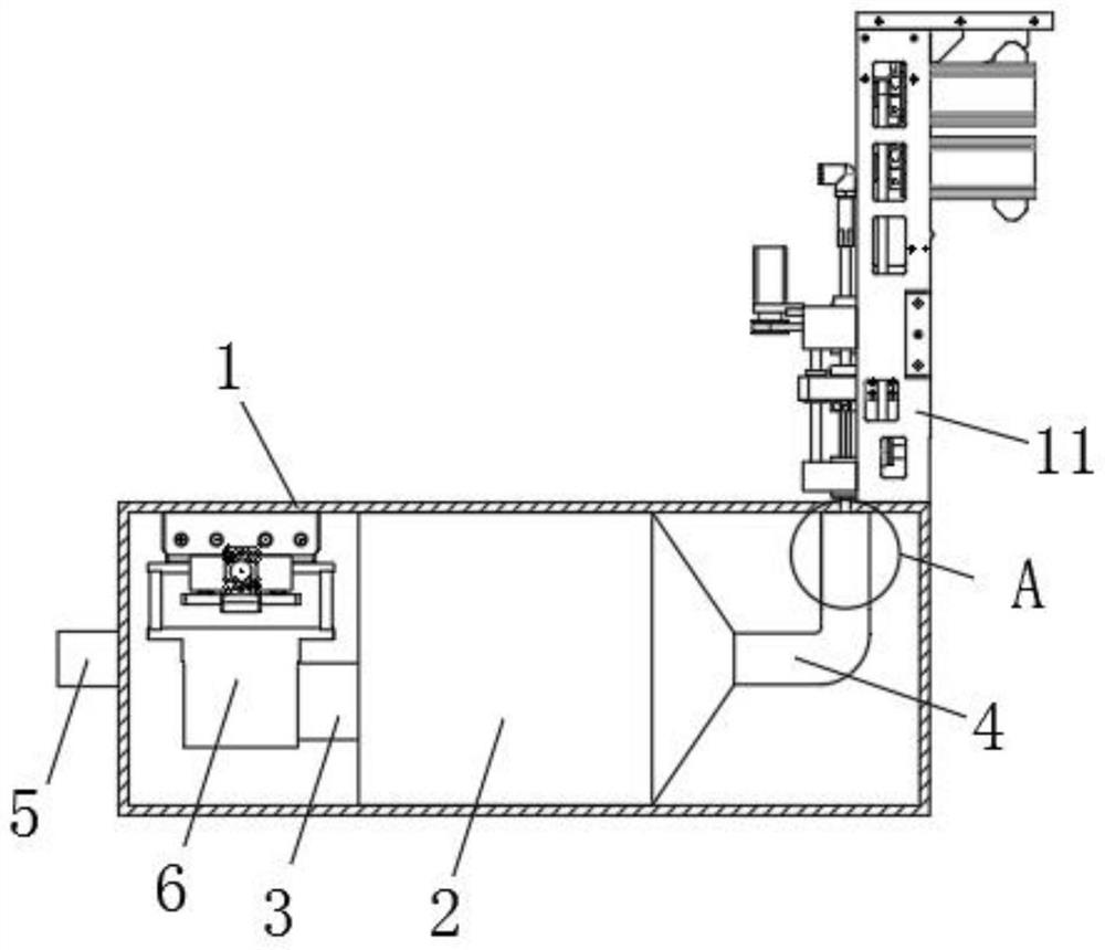
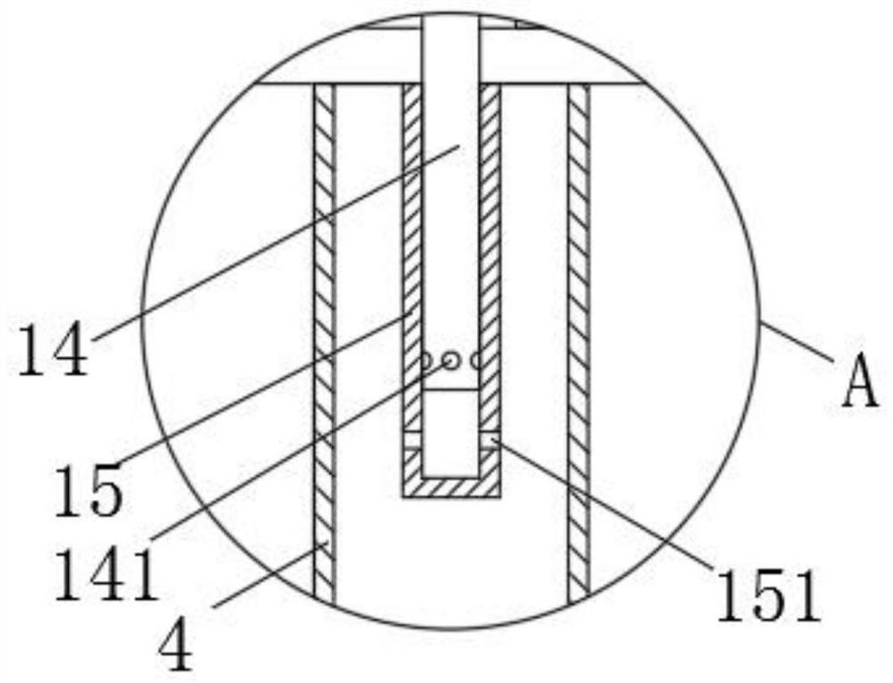
[0034] Such as Figure 1-6 As shown, a flow control structure of a nitrogen-oxygen separation device includes a housing 1, one end of the housing 1 is provided with an air inlet 5, and the upper inner wall of the housing 1 is installed near the end of the air inlet 5 A flow limiting assembly 6, a molecular sieve 2 is fixedly installed inside the housing 1, an inlet pipe 3 is provided at one end of the molecular sieve 2 close to the flow limiting assembly 6, and an outlet pipe 4 is provided at the other end of the molecular ...


PUM


Abstract

The invention discloses a flow control structure of a nitrogen-oxygen separation device. The device includes a shell, an air inlet is formed at one end of the shell, a flow limiting assembly is installed on the inner wall of the upper side of the shell, a molecular sieve is fixedly mounted on the inner side of the shell, a guide-in pipe is arranged at the end, close to the flow limiting assembly,of the molecular sieve, a guide-out pipe is arranged at the other end of the molecular sieve, a supporting vertical plate is installed on the upper surface of the shell, a plurality of air outlet pipes are movably installed on one side of the supporting vertical plate, and a fixing pipe is fixedly installed on the inner wall of the upper side of the shell and located on the inner side of the guide-out pipe; according to the invention, the purpose of controlling the flow of gas entering the guide-in pipe can be achieved, so that the nitrogen-oxygen mixed gas separation rate is controlled, so that separation of the nitrogen-oxygen mixed gas is precisely controlled, the amount of discharged oxygen can be controlled, meanwhile, the oxygen requirements of multiple positions are met, manual assistance is not needed in the flow control process, the labor intensity is reduced, and the working efficiency is improved.

Description

technical field [0001] The invention relates to the technical field of oxygen generators, in particular to a flow control structure of a nitrogen and oxygen separation device. Background technique [0002] The principle of the oxygen generator is to use the air separation technology, first compress the air with high density and then use the difference in the condensation point of each component in the air to separate the gas and liquid at a certain temperature, and then further rectify it; Oxygen machine working principle: using molecular sieve physical adsorption and desorption technology. The oxygen concentrator is filled with molecular sieves, which can absorb nitrogen in the air when pressurized, and the remaining unabsorbed oxygen is collected and purified to become high-purity oxygen. At present, most medical oxygen concentrators use PSA (pressure swing adsorption) air separation oxygen production technology, which is based on the difference in the adsorption capacity...

Claims


Application Information

Patent Timeline
IPC IPC(8): B01D53/047C01B13/02
CPCB01D53/047C01B13/0262C01B2210/0046
Inventor 郭本胜李海洋
Owner 安徽康居人健康科技有限公司
Why Eureka
Try Eureka