Engineering ship full-rotation main thruster installation process

An installation process and full rotation technology, applied in the direction of ships, etc., can solve the problems of heavy non-routine installation and high main thruster height, and achieve the effect of ensuring construction quality and safety.

Active Publication Date: 2020-11-06
JIANGSU UNIV OF SCI & TECH
View PDF9 Cites 3 Cited by
  • Summary
  • Abstract
  • Description
  • Claims
  • Application Information

AI Technical Summary

Problems solved by technology

[0003] Purpose of the invention: In order to overcome the deficiencies in the prior art, the present invention provides a main thruster installation pro

Method used


Image

  • Engineering ship full-rotation main thruster installation process
  • Engineering ship full-rotation main thruster installation process
  • Engineering ship full-rotation main thruster installation process

Examples


Embodiment

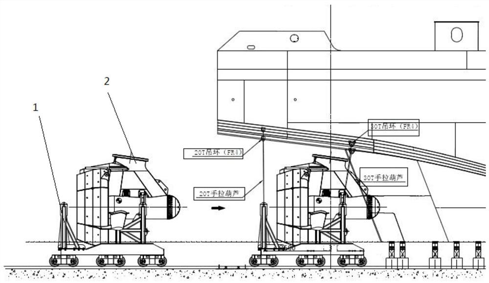
[0062] The installation process of the full-slewing main thruster of an engineering ship of the present invention is characterized by including the following steps:

[0063] Step 1: Make a suitable main thruster base, which includes a flange and a cylindrical web;

[0064] Step 2: Install the main booster base:

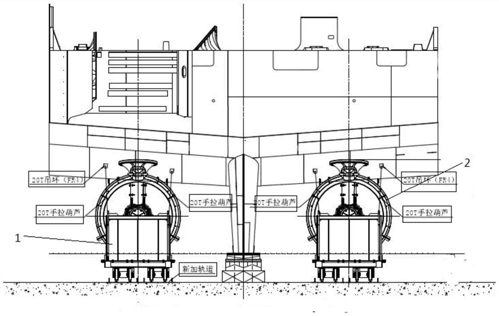
[0065] (1) Before the flange is hoisted, use the sample punch to make the cross center line on the flange panel, and at the same time make the bottom cross center line punch point on the round pass of the flange. Spot weld an angle steel at each of the upper and lower flange ports, find the upper and lower center points on the angle steel according to the punching point, and drill holes on the punching point;

[0066] (2) Draw the ground sample line. According to the theoretical data, draw the center line of the upper flange plate and the cross center line of the lower cylinder on the berth. If the hull shell has not been drilled at this stage, simple openings can be made in ...


PUM


Abstract

The invention discloses an engineering ship main thruster installation process which comprises the following steps that 1, an applicable main thruster base is manufactured, and the main thruster basecomprises a flange plate and a cylindrical web plate; 2, a main pusher base is installed; 3, butt welding is conducted on the T-shaped beam extending out of the periphery of the flange plate in the step 2 and a T-shaped beam structure of a ship body; 4, a main thruster is installed, wherein the main thruster is divided into a propelling module, a steering module and an auxiliary and cooling module; 5, a steering module is installed; 6, a propelling module is installed; 7, installation of an auxiliary and cooling module; according to the process, the conventional mounting method of drilling from a deck and hoisting the propeller from the upper part by a crane is changed, the propeller is located on the special tray and is mounted in a manner of being held from bottom to top, and the problemthat the device is ultrahigh and overweight and cannot be conventionally mounted is well solved.

Description

Technical field [0001] The invention relates to an installation process of an all-slewing main thruster, in particular to an installation process of an all-slewing main thruster of an engineering ship, and belongs to the technical field of ship manufacturing. Background technique [0002] The azimuth main thruster of the engineering ship integrates the power motor body into the inside of the pod, and the power cable is connected and transmitted through the shaft slip ring. The output shaft of the motor in the pod directly drives the propeller, and the outer ring of the propeller is designed with a deflector to improve the efficiency of the propeller. The pod body is flat and wide, which can play the role of "rudder". With such a complicated design, for the ship propeller diameter φ3500mm, the weight of a single propeller unit reaches 56T, and the net height of the equipment is 6340mm. Due to the larger volume of the equipment, the diameter of the structural base flange is also l...

Claims


Application Information

Patent Timeline
IPC IPC(8): B63B73/20
CPCB63B73/20
Inventor 周宏李荣吴承恩蔡灵
Owner JIANGSU UNIV OF SCI & TECH
Why Eureka
Try Eureka