
Blast furnace hearth and blast furnace hearth pouring long life prolonging method

A blast furnace and hearth technology, which is applied in the field of blast furnace hearth and its casting longevity improvement field, can solve the problems of shortening the casting life of the hearth, affecting the heat transfer of the hearth, and reducing the heat transfer effect, so as to improve the casting effect, The heat transfer effect is good, and the effect of improving the longevity of the hearth

Inactive Publication Date: 2020-11-06
SGIS SONGSHAN CO LTD
View PDF5 Cites 4 Cited by
  • Summary
  • Abstract
  • Description
  • Claims
  • Application Information

AI Technical Summary

Problems solved by technology

If these gaseous water and condensed water cannot be discharged from the furnace body in time, the heat transfer effect between the new casting material of the furnace hearth and the carbon brick, the ramming layer between the carbon brick and the cooling wall, and the cooling wall will be greatly reduced. New castables will be eroded faster, resulting in shortened hearth pouring life
Therefore, if gaseous water and condensed water are formed during hearth pouring, if they are not discharged out of the hearth in time, it will affect the overall heat transfer of the hearth, resulting in a significant shortening of the life of the hearth after pouring. However, there is no blast furnace in the existing blast furnace technology Hearth and its casting longevity improvement method

Method used


Image

  • Blast furnace hearth and blast furnace hearth pouring long life prolonging method

Examples


Embodiment

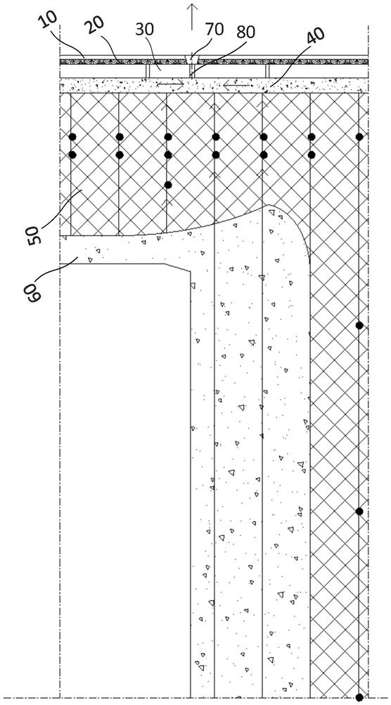
[0045] The present invention has been used in Baowu Group Shaoguan Iron and Steel 1050m 3 Blast furnace hearth quick repair upper matching application. In the hearth cleaning process of the blast furnace, there are 12 holes drilled in the hearth area, and the depth of the holes is 250mm (the thickness of the furnace shell 10 is 50mm+the thickness of the pouring layer 20 between the furnace shell 10 and the stave 30 is 40mm+ The thickness of the stave 30 is 160 mm); the furnace hearth is poured and the middle stage of baking is started to open the drain valve successively for exhausting and draining. In the later stage of baking (total baking 108 hours), there are 6 drain valves with continuous discharge of air or water. Anhydrous carbon material (resin bonded) is selected as the press-in material, and the single press-in quantity is controlled to be ≤50kg, with a total press-in of 210kg; at present, it has been in production for more than half a year, and the heat transfer ef...


PUM


Abstract

The invention relates to a blast furnace hearth and a blast furnace hearth pouring long life prolonging method. The blast furnace hearth comprises a furnace shell, a pouring layer, a cooling wall, a ramming layer, carbon bricks and a furnace hearth pouring layer. The side walls of the furnace shell, the pouring layer, the cooling wall, the ramming layer, the carbon bricks and the furnace hearth pouring layer are arranged in sequence from outside to inside, and the furnace bottoms of the furnace hearth pouring layer and the carbon bricks are arranged from top to bottom. The method comprises thesteps that after the charge level is lowered, the water fetching amount for cooling furnace hearth scrap iron in slag is controlled through intermittent water fetching operation and evaporation cooling operation; a first drill hole and a second drill hole are formed in the furnace hearth region according to the thickness calculation of the furnace shell, the pouring layer and the cooling wall, and the first drill hole and the second drill hole communicate with each other; a press-in short pipe is arranged in the first drill hole, a valve is installed on the short pipe to be used for follow-upair exhaust, drainage and press-in operation, and the valve is closed after the operation is accomplished; baking operation is conducted after furnace hearth pouring operation is accomplished, and drain valves are sequentially opened to conduct air exhaust and drainage; and the baking operation of the furnace hearth is accomplished, and carbon quality materials are pressed into the cooling wall and the ramming layer by the press-in short pipe in the blowing-in material charging process after the drain valves are opened to drain water.

Description

technical field [0001] The invention relates to the technical field of blast furnace technology, more specifically, it relates to a blast furnace hearth and a method for improving the casting longevity of the hearth. Background technique [0002] At present, the iron-making industry is very sure of the various hazards of water to the hearth carbon bricks, and tries to reduce the water intake in the hearth during production. More and more rapid repairs of the existing blast furnace hearth are carried out by pouring, that is, after the blast furnace has finished lowering the material level, in order to achieve the purpose of shortening the construction period and quick repair, before the hearth is ready for construction, the method of cooling the furnace with water is adopted. The method quickly lowers the temperature of the high-temperature slag and iron in the hearth. During the process of pumping water to cool the furnace, part of the water overflowed the blast furnace in ...

Claims


Application Information

Patent Timeline
IPC IPC(8): C21B7/06C21B7/10
CPCC21B7/06C21B7/10
Inventor 杨国新李国权王忠连凌志宏廖经文柏徳春吴金富庄锦填黄恺王振
Owner SGIS SONGSHAN CO LTD
Learn More