Constrained high-speed dynamic balance mechanical calculation method

A high-speed dynamic balance and mechanics technology, applied in the field of dynamic balance mechanics solution, can solve the problems such as failure to effectively ensure whether the intensity value meets the requirements, the implementation process is heavy, and the overall energy of the system is reduced, so as to achieve both operability and ease of use performance, improve dynamic balance accuracy, and ensure smooth operation.

Active Publication Date: 2020-11-06
TIANJIN UNIV +1
View PDF7 Cites 2 Cited by
  • Summary
  • Abstract
  • Description
  • Claims
  • Application Information

AI Technical Summary

Problems solved by technology

[0003] At present, with the technical transformation of turbomachinery rotors from slow turbines to fast turbines, the traditional dynamic balancing method has shown certain deficiencies. As the working speed increases, the rigid body assumption cannot be realized; while the influence coefficient method is applicable to high-speed dynamic balance conditions, but the influence coefficient method uses the mean square sum of the measured amplitude as the objective function, and the implementation process is heavy, requiring the overall energy of the system to be reduced. However, it fails to effectively guarantee whether the intensity value at the critical speed meets the requirements
[0004] The objective function of the existing unbalance method is to reduce the overall vibration amplitude of the system, which fails to effectively guarantee whether the intensity value at the critical speed meets the requirements

Method used


Image

  • Constrained high-speed dynamic balance mechanical calculation method
  • Constrained high-speed dynamic balance mechanical calculation method
  • Constrained high-speed dynamic balance mechanical calculation method

Examples


Embodiment

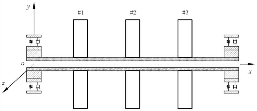
[0062] figure 1 Shown is that the model is the axial flow compressor rotor of AV50, and it is used as the embodiment object of the present invention, and the parameters needed in the dynamic balance include:

[0063] The number of correction surfaces: This type of rotor has full-circle balance slots reserved on both sides of the shaft section during production and processing, and a screw hole is reserved in the middle of the shaft end for installation of balance weights. Therefore, the number of correction surfaces that can be used is Three, such as figure 1 #1, #2, and #3 respectively represent the three surfaces that can be corrected;

[0064] The number of measuring points: Use the 50-ton high-speed balancing machine produced by Shenke Company for dynamic balancing. At present, there are only two supporting pendulums at the measuring points, so the number of measuring points is two;

[0065] Calibration speed: The dynamic balancing process uses speed up and down, and the ...


PUM


Abstract

The invention discloses a constrained high-speed dynamic balance mechanical calculation method, which comprises the following steps of: calculating an influence coefficient through driving, trial weight and measurement, and establishing an influence coefficient matrix; establishing a Lagrange function according to constraint conditions of a dynamic balance standard: solving a counterweight optimalvalue by utilizing a KKT condition; and adding and reducing weight, and driving to correct a dynamic balance result. By adding constraints to the intensity value at the key rotating speed, the intensity value of the key rotating speed is further reduced on the premise of ensuring overall vibration reduction, and stable operation of the rotor is ensured. The method provided by the invention is suitable for dynamic balance mechanical calculation of turbomachinery rotors which have high requirements on residual unbalance and of which the working rotating speed at least exceeds a first-order critical rotating speed. And low-cost operability of constrained high-speed dynamic balance calculation can be realized. Operators only need to input the magnitude of the constraint intensity value on a program panel, and the magnitude and phase of the balance weight and the estimated value of the residual unbalance amount can be obtained through full-automatic calculation and analysis of a program.

Description

technical field [0001] The invention relates to a method for solving dynamic balance mechanics. In particular, it relates to a constrained high-speed dynamic balance mechanics solution method suitable for turbomachinery rotors. Background technique [0002] Dynamic balance is an important part of the inspection and correction of turbine machinery before leaving the factory. By performing dynamic balance (weight addition and weight reduction) correction on the rotor, the fundamental frequency vibration caused by the unbalance caused by factors such as manufacturing tolerances can be reduced. Usually, the dynamic balance before leaving the factory is carried out based on the dynamic balance testing machine, and the rotor needs to undergo dynamic balance correction before it can continue to serve after remanufacturing. The traditional dynamic balance theory is quite mature. For low-speed dynamic balance (rigid dynamic balance), the ABC method is usually used, while for high-sp...

Claims


Application Information

Patent Timeline
Patent Type & Authority Applications(China)
IPC IPC(8): G06F30/20G06F30/17G06F17/16G01M1/36
CPCG06F30/20G01M1/36G06F17/16G06F30/17Y02T90/00
Inventor 钟顺路振勇陈会征韩佳杰王超
Owner TIANJIN UNIV
Why Eureka
Try Eureka