Dielectric filter with 180-degree phase shifter

A dielectric filter and phase shifter technology, applied in resonators, waveguide-type devices, electrical components, etc., to overcome the complexity of filter design, easy miniaturization, and convenient design.

Active Publication Date: 2020-11-06
人民华智通讯技术有限公司
View PDF7 Cites 0 Cited by
  • Summary
  • Abstract
  • Description
  • Claims
  • Application Information

AI Technical Summary

Problems solved by technology

[0006] The purpose of the present invention is to address the deficiencies of the above-mentioned prior art, and propose a dielectric filter with a 180-degree phase shifter, which is used to solve the problem of flexibly changing the original coupling polarity when the radio frequency front-end of a wireless communication system performs filtering, and to easily realize cross-coupling filtering machine problem

Method used


Image

  • Dielectric filter with 180-degree phase shifter
  • Dielectric filter with 180-degree phase shifter
  • Dielectric filter with 180-degree phase shifter

Examples


Embodiment 1

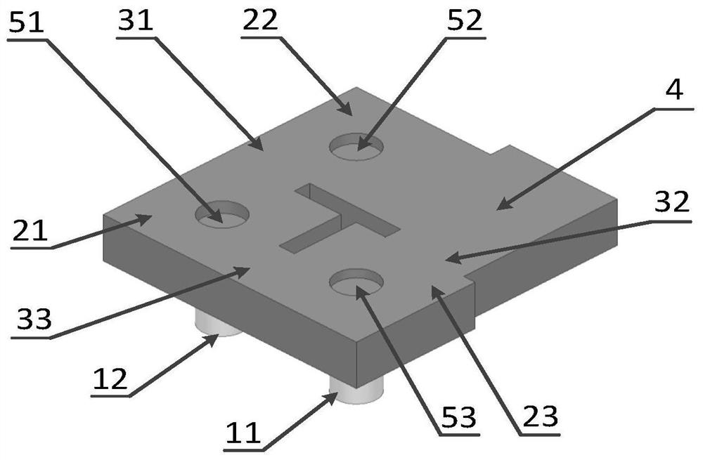
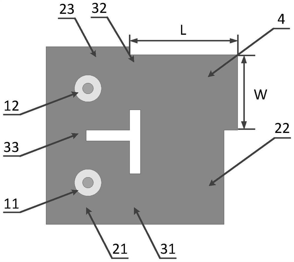
[0043] Combine below figure 1 and figure 2 The shown top side view and bottom view of a three-cavity cascaded cross-coupled dielectric filter with 180-degree phase shifters further describe the present invention.

[0044] Such as figure 1 As shown, the three-cavity cascaded cross-coupled dielectric filter with a 180-degree phase shifter includes an input coaxial connector 11 and an output coaxial connector 12 provided on one side of the lower surface. Three resonators 21, 22, 23, the first dielectric resonator 21 is set in the lower left corner of the dielectric filter, the second dielectric resonator 22 is set in the upper left corner, and the third dielectric resonator 23 is set in the lower right corner, the three dielectric resonators are Cuboid structure, the resonators 21, 22, 23 work in the fundamental mode TE101 mode, three coupling windows 31, 32, 33, wherein the coupling window 31 is placed between the resonators 21 and 22, and the coupling window 33 is placed in ...

Embodiment 2

[0047] Combine below Figure 4 and Figure 5 The shown top side view and bottom view of a four-cavity cascaded cross-coupled dielectric filter with 180-degree phase shifters further describe the present invention.

[0048] Embodiment 1 of the present invention forms transmission zeros on the left band of the dielectric filter, and Embodiment 2 of the present invention forms two transmission zeros simultaneously on the left and right bands of the dielectric filter. exist Figure 4 Among them, the dielectric filter of the present invention includes an input coaxial connector 11 and an output coaxial connector 12 arranged on one side of the lower surface. Four resonators 25, 26, 27, 28, the first dielectric resonator 25 is set in the lower left corner of the dielectric filter, the second dielectric resonator 26 is set in the left side, the third dielectric resonator 27 is set in the upper left corner, and the lower right corner is set The fourth dielectric resonator 28, the fo...

Embodiment 3

[0051] Combine below Figure 7 and Figure 8 The top side view of the three-cavity cascaded cross-coupled dielectric filter with a 180-degree phase shifter and a circular and square debugging hole with a 180-degree phase shifter are shown to further describe the present invention.

[0052] To ensure that the operating frequency of the waveguide transmission line of the 180-degree phase shifter is below the cutoff frequency, there are many ways to implement the 180-degree phase shifter. Example 1 and Example 2 of the present invention use a uniform waveguide transmission line without perturbation. The electrical length of 180 degrees can be calculated analytically according to the θ=β×L formula. Adding a debugging hole can reduce the physical length and size on the basis of the original electrical length. The arbitrary shape of the debugging hole is equivalent to capacitive or inductive loading, which can introduce a phase shift, thereby reducing the size of the overall wavegu...


PUM


Abstract

The invention discloses a dielectric filter with a 180-degree phase shifter. The dielectric filter comprises a plurality of dielectric resonators and the 180-degree phase shifter, wherein the dielectric resonators are connected with one another; the surface of each dielectric resonator and the surface of each 180-degree phase shifter are metal conducting layers, and the interior of each dielectricresonator and the interior of each 180-degree phase shifter are media with any dielectric constants. Each dielectric resonator comprises a debugging hole, and the debugging hole is used for adjustingthe resonant frequency of the resonator; the 180-degree phase shifter is a waveguide transmission line in any shape and cannot contain or contain a plurality of debugging holes, the contained debugging holes are used for reducing the size of the 180-degree phase shifter, and the 180-degree phase shifter is used for changing the polarity of original coupling and achieving cross coupling response of the filter. According to the invention, the polarity of original coupling can be flexibly changed, a cross-coupled filter is easy to realize, the cost is low, the reliability is high, and the dielectric filter with a 180-degree phase shifter can be applied to filter design of modern communication systems.

Description

technical field [0001] The invention relates to the technical field of communication equipment components, and further relates to a dielectric filter with a 180-degree phase shifter in the technical field of radio frequency of wireless communication systems. The invention can flexibly change the original coupling polarity when the radio frequency front end of the wireless communication system performs filtering, and easily realize the cross-coupling filter. Background technique [0002] In recent years, with the rapid development of fifth-generation mobile communications, wireless local area networks, and satellite communications, the utilization rate of wireless spectrum has become higher and higher, and the requirements for miniaturization, high performance, and low cost have been put forward for RF microwave filters in communication systems. . Dielectric waveguide filters can be miniaturized because the dielectric constant of the internal medium can be adjusted. In addit...

Claims


Application Information

Patent Timeline
Patent Type & Authority Applications(China)
IPC IPC(8): H01P1/20H01P1/18H01P7/10
CPCH01P1/182H01P1/2002H01P7/10
Inventor 陈建忠郭超杰魏雅琪赵雨桐吴边
Owner 人民华智通讯技术有限公司
Why Eureka
Try Eureka