
Combiner Based on Microstrip Line Coupling

A technology of microstrip line and combiner, which is applied in the direction of circuits, waveguide devices, transmission systems, etc., can solve the problems of large volume and weight, deterioration of insertion loss, unequal phase, etc., to reduce noise, reduce insertion loss, improve The effect of the signal-to-noise ratio

Active Publication Date: 2021-06-29
武汉博畅通信设备有限责任公司
View PDF8 Cites 0 Cited by
  • Summary
  • Abstract
  • Description
  • Claims
  • Application Information

AI Technical Summary

Problems solved by technology

The segmented LC filter method is complex in structure, difficult to debug, and has a large volume and weight. It is an early implementation method of combiners.
The structure of the 3dB bridge cascading method is relatively simple, and the debugging is not difficult; but with the increase of the number of channels, a large amount of loss of the combiner is lost on the bridge, resulting in a serious deterioration of the insertion loss, and it is impossible to realize a large number of channels. Combiner; and as the number of channels increases, the frequency of the combiner is higher and the frequency band is wider, which will cause problems such as large insertion loss, large fluctuations, and unequal phases of the combiner

Method used


Image

  • Combiner Based on Microstrip Line Coupling
  • Combiner Based on Microstrip Line Coupling
  • Combiner Based on Microstrip Line Coupling

Examples


Embodiment 1

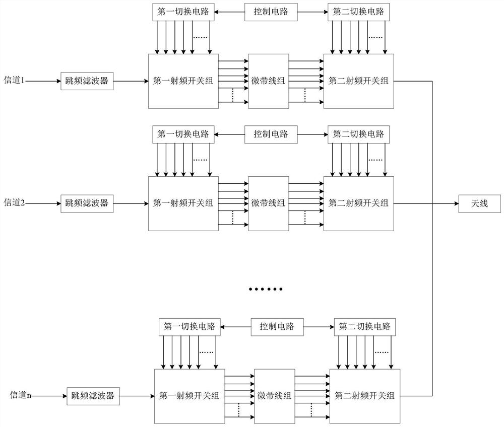
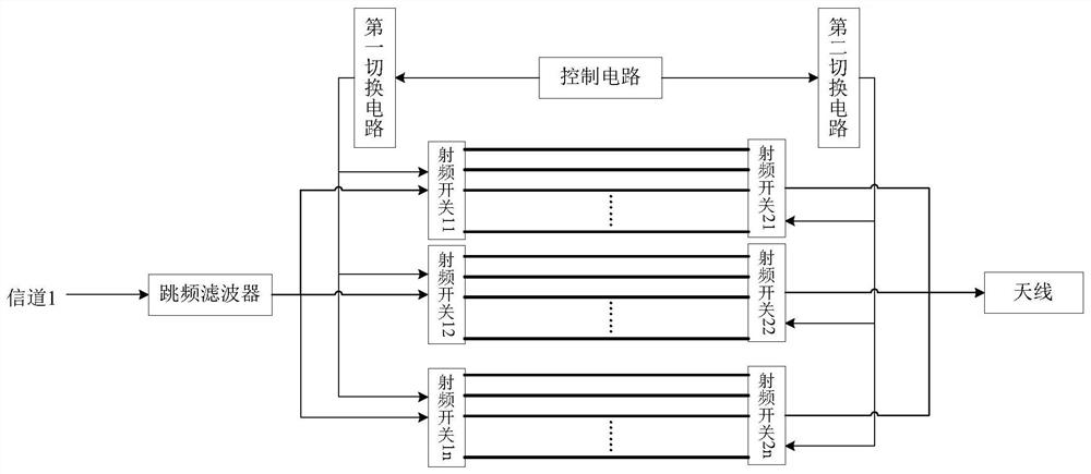
[0030] like figure 1 As shown, the combiner based on microstrip line coupling of the present invention includes N channels and antennas. Each channel includes a frequency hopping filter, a first radio frequency switch group, a second radio frequency switch group, a microstrip line group, a control circuit, a first switching circuit and a second switching circuit.

[0031] Frequency hopping filter, as an important part of frequency hopping communication, is used to realize frequency hopping in different frequency bands, and only allows signals in a certain frequency range to pass through, improving the anti-interference ability of communication; from the signal received by the antenna, the filter The interference spectrum is removed to obtain an effective spectrum, thereby improving the signal-to-noise ratio of the frequency hopping communication system. In this embodiment, the frequency hopping range of the frequency hopping filter in each channel is different.

[0032] The ...

Embodiment 2

[0041] On the basis of Embodiment 1, this embodiment provides a method for designing a microstrip line.

[0042] Further preferably, in order to filter out the interference spectrum in the input signal and obtain an effective spectrum, thereby improving the signal-to-noise ratio of the combiner and reducing the insertion loss, in this embodiment, the number of microstrip lines in the microstrip line group is limited . Preferably, the number of microstrip lines satisfies the formula: F1+(n-2)ΔF=F2;

[0043] In the formula, n is the number of microstrip lines and is greater than 2. If the calculated n is a decimal, n takes the integer before the decimal point; F1 is the lower limit frequency of the frequency hopping filter working bandwidth; F2 is the frequency hopping filter The upper limit frequency of the working bandwidth; ΔF is the bandwidth between adjacent microstrip lines, where ΔF=F 0 ×20%, F 0 Center frequency for the operating bandwidth of the frequency hopping fil...


PUM


Abstract

The invention proposes a combiner based on microstrip line coupling. By setting up a microstrip line group, the working bandwidth of the frequency hopping filter can be further divided into several narrow bandwidths of equal width, and the bandwidth between adjacent microstrip lines Different, only the signals whose frequencies are within the bandwidth are allowed to pass, the interference spectrum in the input signal can be filtered out, and the effective spectrum can be obtained, thereby improving the signal-to-noise ratio of the combiner and reducing the insertion loss; by limiting the length and width of the microstrip line , the characteristic impedance of the microstrip line can be completely matched with the impedance of the receiving element, so that the transmitted signal energy can be completely transmitted.

Description

technical field [0001] The invention relates to the field of combiners in the field of frequency hopping communication, in particular to a combiner based on microstrip line coupling. Background technique [0002] The combiner is mainly used in frequency hopping communication. It can share one antenna with multiple communication stations to realize simultaneous transmission and reception at different frequencies. There are two ways to realize the combiner at present: the subsection LC filter method and the 3dB bridge cascade method. The segmented LC filter method is complex in structure, difficult to debug, and has a large volume and weight. It is an early implementation method of combiners. The structure of the 3dB bridge cascading method is relatively simple, and the debugging is not difficult; but with the increase of the number of channels, a large amount of loss of the combiner is lost on the bridge, resulting in a serious deterioration of the insertion loss, and it is ...

Claims


Application Information

Patent Timeline
Patent Type & Authority Patents(China)
IPC IPC(8): H01P1/213H04B1/52
CPCH01P1/213H04B1/52
Inventor 徐信蔡楚才
Owner 武汉博畅通信设备有限责任公司
Learn More