Eureka AIR delivers breakthrough ideas for toughest innovation challenges, trusted by R&D personnel around the world.

Transmission network fault detection method, device and system

A technology of transmission network and detection method, which is applied in the direction of transmission system, digital transmission system, data exchange network, etc., and can solve problems such as inability to meet production needs, inability to guarantee finding the optimal solution, and prone to errors

Pending Publication Date: 2020-11-06
CHINA UNITED NETWORK COMM GRP CO LTD
View PDF3 Cites 4 Cited by
  • Summary
  • Abstract
  • Description
  • Claims
  • Application Information

AI Technical Summary

Problems solved by technology

But the time complexity of this algorithm is O(N 2 ), it is not guaranteed to find the optimal solution, and when the depth limit is unreasonable, the solution may not be found
[0004] In addition, through the collection and transmission of basic attribute data of network elements and the connection relationship between network elements, the operation distinguishes logical organization structures such as loops and single chains. If large-scale networks and complex networking situations are encountered, the operation efficiency and accuracy are very low. unable to meet production needs
And with the variety of system transmission network structures and complex expansion, the efficiency of complex interactive search is low. In addition, through manual participation, such as manual monitoring and identification processing, manual dispatch of work orders, manual notification of information, and manual interactive alarm status during maintenance, the whole process Manual participation will lead to the dispatch of work orders and information notifications that are not fast enough and timely, and are prone to errors

Method used


Image

  • Transmission network fault detection method, device and system
  • Transmission network fault detection method, device and system
  • Transmission network fault detection method, device and system

Examples


Embodiment Construction

[0046]In order to make the purpose, technical solutions and advantages of the embodiments of the present invention clearer, the technical solutions in the embodiments of the present invention will be clearly and completely described below in conjunction with the drawings in the embodiments of the present invention. Obviously, the described embodiments It is a part of embodiments of the present invention, but not all embodiments. Based on the embodiments of the present invention, all other embodiments obtained by persons of ordinary skill in the art without making creative efforts belong to the protection scope of the present invention.

[0047] The terms "first", "second", "third", "fourth", etc. (if any) in the description and claims of the present invention and the above drawings are used to distinguish similar objects, and not necessarily Used to describe a specific sequence or sequence. It is to be understood that the data so used are interchangeable under appropriate cir...


PUM


Abstract

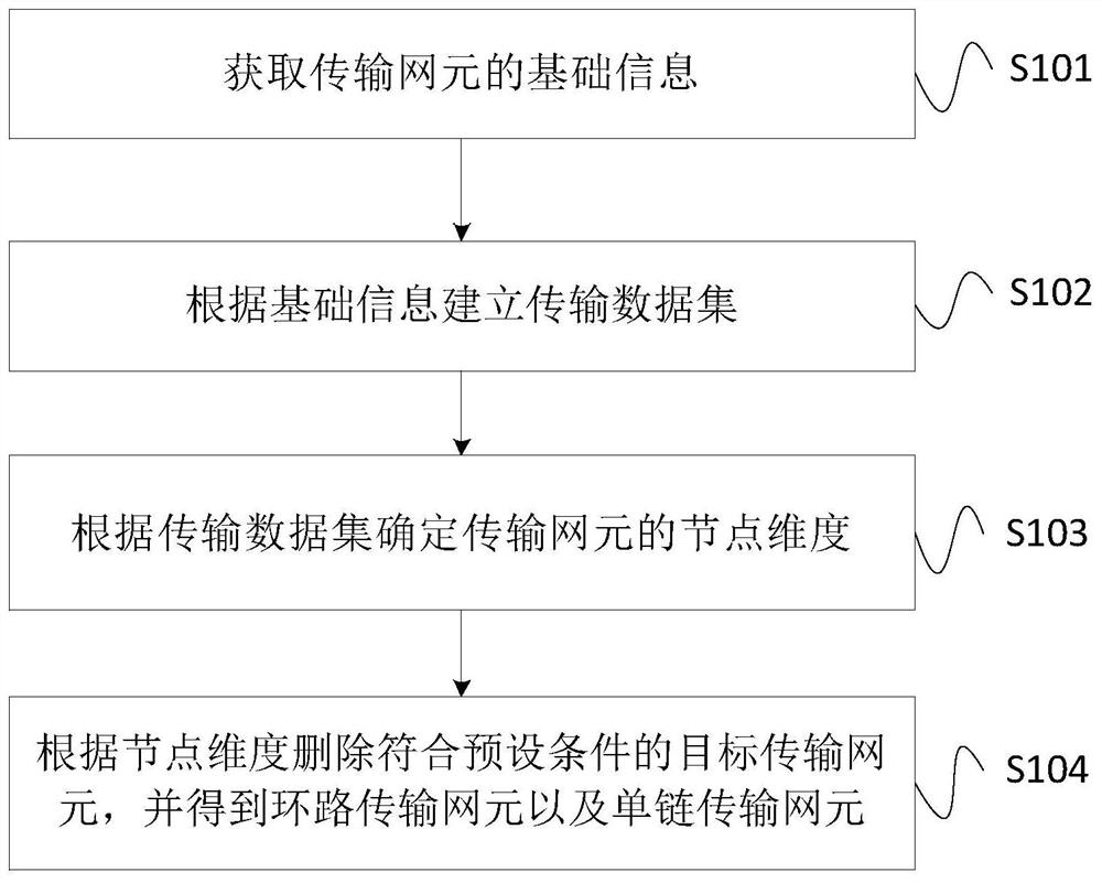
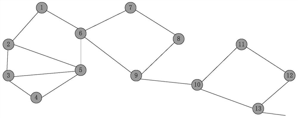
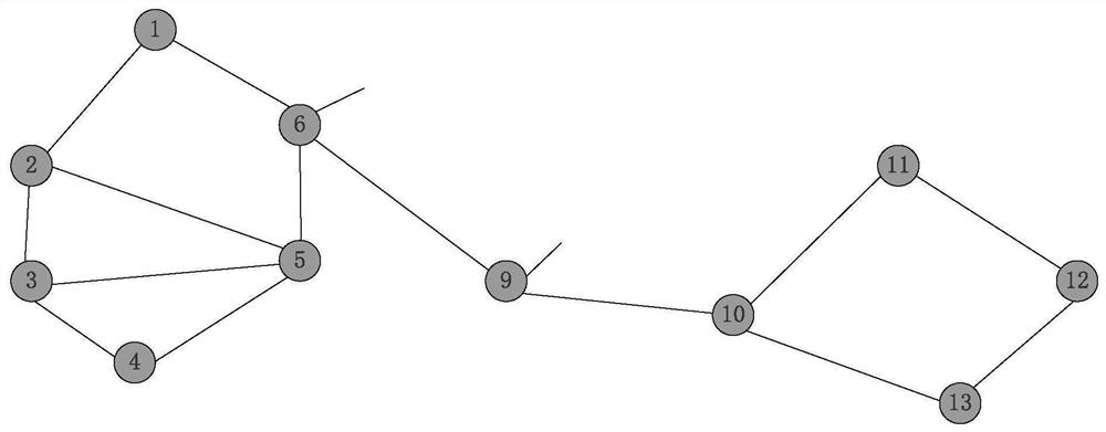
The invention provides a transmission network fault detection method, device and system. The method comprises the following steps: acquiring basic information of a transmission network element; establishing a transmission data set according to the basic information, wherein the transmission data set comprises a plurality of pieces of basic information; determining a node dimension of the transmission network element according to the transmission data set, wherein the node dimension is used for representing a matrix feature of the transmission data set; deleting the target transmission networkelement meeting a preset condition according to the node dimension, and obtaining a loop transmission network element and a single-chain transmission network element; wherein the loop network elementis a network element which only influences a link corresponding to the loop network element, and the single-chain transmission network element is a network element which influences an overall link, sothat the influence of a transmission network fault on the overall link is detected. The invention achieves the better effects of quicker transmission network fault detection, high accuracy, low cost,time and labor saving, high efficiency and the like.

Description

technical field [0001] The present invention relates to technical fields such as computer network transmission, and in particular to a detection method, device and system for transmission network faults. Background technique [0002] The transmission network is the carrier's basic network, and if it fails, it will seriously affect the carrier's network operations. In network communication, the transmission network has a wide coverage area, a large number of network elements, and poor geographical deployment conditions. There are various factors that will cause transmission network failures, which makes it difficult to alarm and monitor information and fault diagnosis of the transmission network. For example, transmission When the network fails, it is difficult to identify effective alarms and the alarm processing efficiency is low. It is difficult for the system to associate the network topology with alarms. Manual monitoring and processing of alarms are inefficient and erro...

Claims


Application Information

Patent Timeline
IPC IPC(8): H04L12/26H04L12/24
CPCH04L41/0677H04L41/0886H04L43/04H04L43/08
Inventor 李明欣霍明德及莹周国语
Owner CHINA UNITED NETWORK COMM GRP CO LTD
Why Eureka
Eureka Blog
Learn More