Eureka AIR delivers breakthrough ideas for toughest innovation challenges, trusted by R&D personnel around the world.

Annular shrinking device and mounting method thereof

A ring constrictor and fixed ring technology, which is applied in the field of medical devices, can solve the problems of traumatic treatment of mitral valve regurgitation, increase the difficulty of surgery, prolong the operation time, etc., so as to reduce the operation cost, reduce the operation trauma, and restore tissue fast effect

Inactive Publication Date: 2020-11-10
SHANGHAI HONGYU MEDICAL TECH CO LTD
View PDF0 Cites 1 Cited by
  • Summary
  • Abstract
  • Description
  • Claims
  • Application Information

AI Technical Summary

Problems solved by technology

[0003] For the treatment of mitral valve regurgitation, a ring reducer is needed. However, the traditional ring reducer has a simple structure, a single function, and complicated operation. Moreover, the traditional ring reducer is mostly rigid, which increases the difficulty of the operation and prolongs the operation time. , thus causing unnecessary harm to the patient; secondly, the traditional constrictor is not equipped with a puncture needle device, which makes the treatment of mitral valve regurgitation more traumatic; therefore, there is an urgent need for an elastic or flexible ring shrinker

Method used


Image

  • Annular shrinking device and mounting method thereof
  • Annular shrinking device and mounting method thereof
  • Annular shrinking device and mounting method thereof

Examples


Embodiment Construction

[0028] The following will clearly and completely describe the technical solutions in the embodiments of the present invention with reference to the accompanying drawings in the embodiments of the present invention. Obviously, the described embodiments are only some, not all, embodiments of the present invention. Based on the embodiments of the present invention, all other embodiments obtained by persons of ordinary skill in the art without making creative efforts belong to the protection scope of the present invention.

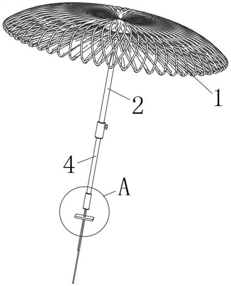
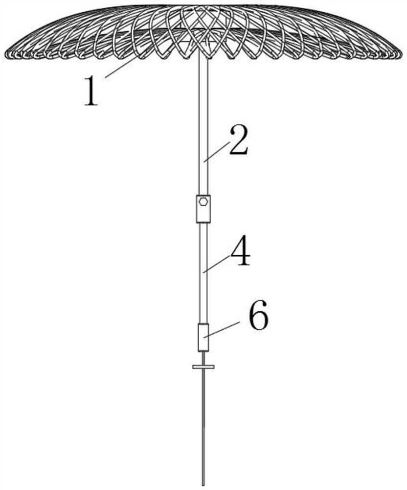
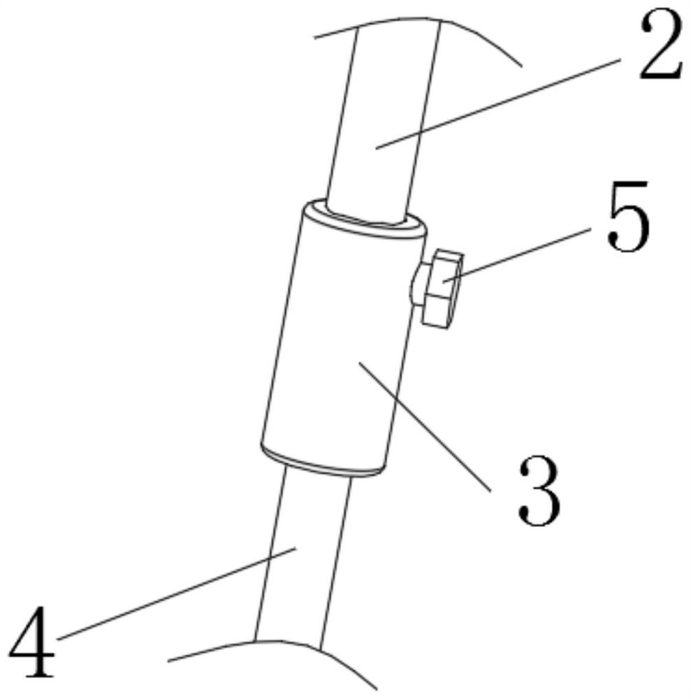
[0029] The present invention provides such Figure 1-6 The shown is applied to a mitral valve constrictor, which includes a occlusion piece 1 , a puncture tube 2 , a push rod 4 , a column 6 , a hemostatic disk 7 , a first puller wire 8 , a second puller wire 9 and a fixing ring 10 .

[0030] Connection relationship: the occlusion piece 1 has a shape memory function, and can be pressed into a sheath tube of a smaller size. The occlusion piece is fixed by the fi...


PUM


Abstract

The invention discloses an annular shrinking device and a mounting method thereof, and relates to the field of medical instruments. The annular shrinking device comprises a plugging sheet, a hemostatic disc, a puncture tube and a push rod, wherein one end of the push rod penetrates through an inner cavity of the puncture tube and extends out of the inner cavity of the puncture tube; the push rod is used for pushing out the plugging piece in the puncture tube to be propped open; and the hemostatic disc is further arranged at pull wires to be connected with the plugging piece. The distance between the plugging piece and the hemostatic disc can be effectively adjusted through the pull wires, and therefore the annular shrinking effect is achieved. The device is reasonable in structure; throughthe flexible design of the plugging sheet, operative wounds are small, tissue recovery is fast, and the purpose of treating reflux is achieved; the pull wires are made of high polymer materials, thesurface is smooth, and the minimally invasive purpose can be achieved; and instruments are small, smooth round pipe conveying is adopted, the path is simple, an operation is easy to operate, and production, research and development are easy to achieve, so that the operation cost is reduced.

Description

technical field [0001] The invention relates to the field of medical devices, in particular to a ring constrictor used in auxiliary mitral valve surgery and an installation method thereof. Background technique [0002] The mitral valve is the left atrioventricular valve, also known as the mitral valve. It is attached to the left fibrous atrioventricular ring and is formed by the folds of the endocardium. There are two valves, the one located on the anteromedial side is the anterior cusp The larger, often called the large valve, is the boundary mark between the inflow tract and the outflow tract of the left ventricle. The one located on the posterolateral side is the posterior cusp valve, and the smaller one is often called the small valve. The bottom edges are often fused with each other, and sometimes a small secondary valve appears between the two valves. There are many tendons connected to the papillary muscle at the tip, edge and chamber surface. When the ventricle contr...

Claims


Application Information

Patent Timeline
Patent Type & Authority Applications(China)
IPC IPC(8): A61F2/24
CPCA61F2/2487
Inventor 戴宇峰潘炳跃王智杰潘文志
Owner SHANGHAI HONGYU MEDICAL TECH CO LTD
Why Eureka
Eureka Blog
Learn More