
Uniform drying mechanism of coating oven

An oven and drying technology, which is applied to the device, coating, pretreatment surface, etc. for coating liquid on the surface, can solve the problems of easy relaxation of the pole piece, quality problems of coated products, unstable hot air, etc. The oven is hygienic, easy to operate and simple in structure

Active Publication Date: 2020-11-10
HEFEI GUOXUAN HIGH TECH POWER ENERGY
View PDF12 Cites 3 Cited by
  • Summary
  • Abstract
  • Description
  • Claims
  • Application Information

AI Technical Summary

Problems solved by technology

However, the air nozzle structure of the floating oven used in the current market is mainly arranged vertically and staggeredly. The distance between the upper and lower air nozzles is 10mm-30mm. The hot air from the air nozzle forms an air cushion between the pole pieces, and the pole pieces are held up to ensure that the pole pieces are dry and clean. The operation is stable, but when the coating machine is started and stopped, the pole piece is prone to slack due to the tension, or the hot air discharged from the air outlet of the air nozzle is unstable, and the pole piece is prone to gap between the pole piece and the protruding air nozzle. Scratches caused by contact, causing problems in the quality of coated products
At the same time, due to the characteristics of the continuous production line, it is necessary to maintain and clean the sanitation of the oven regularly to prevent foreign matter from blocking the air outlet of the tuyere, making it difficult to clean and causing secondary pollution of the new pole piece.

Method used


Image

  • Uniform drying mechanism of coating oven
  • Uniform drying mechanism of coating oven
  • Uniform drying mechanism of coating oven

Examples


Embodiment Construction

[0033] The following will clearly and completely describe the technical solutions in the embodiments of the present invention with reference to the accompanying drawings in the embodiments of the present invention. Obviously, the described embodiments are only some, not all, embodiments of the present invention. Based on the embodiments of the present invention, all other embodiments obtained by persons of ordinary skill in the art without making creative efforts belong to the protection scope of the present invention.

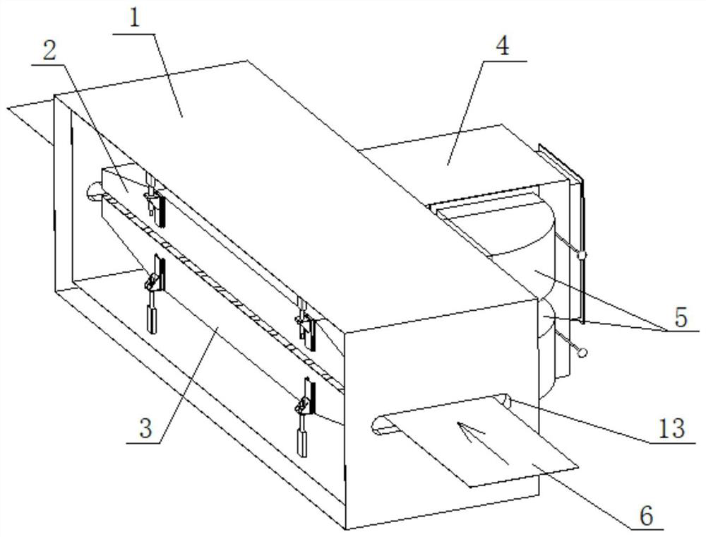
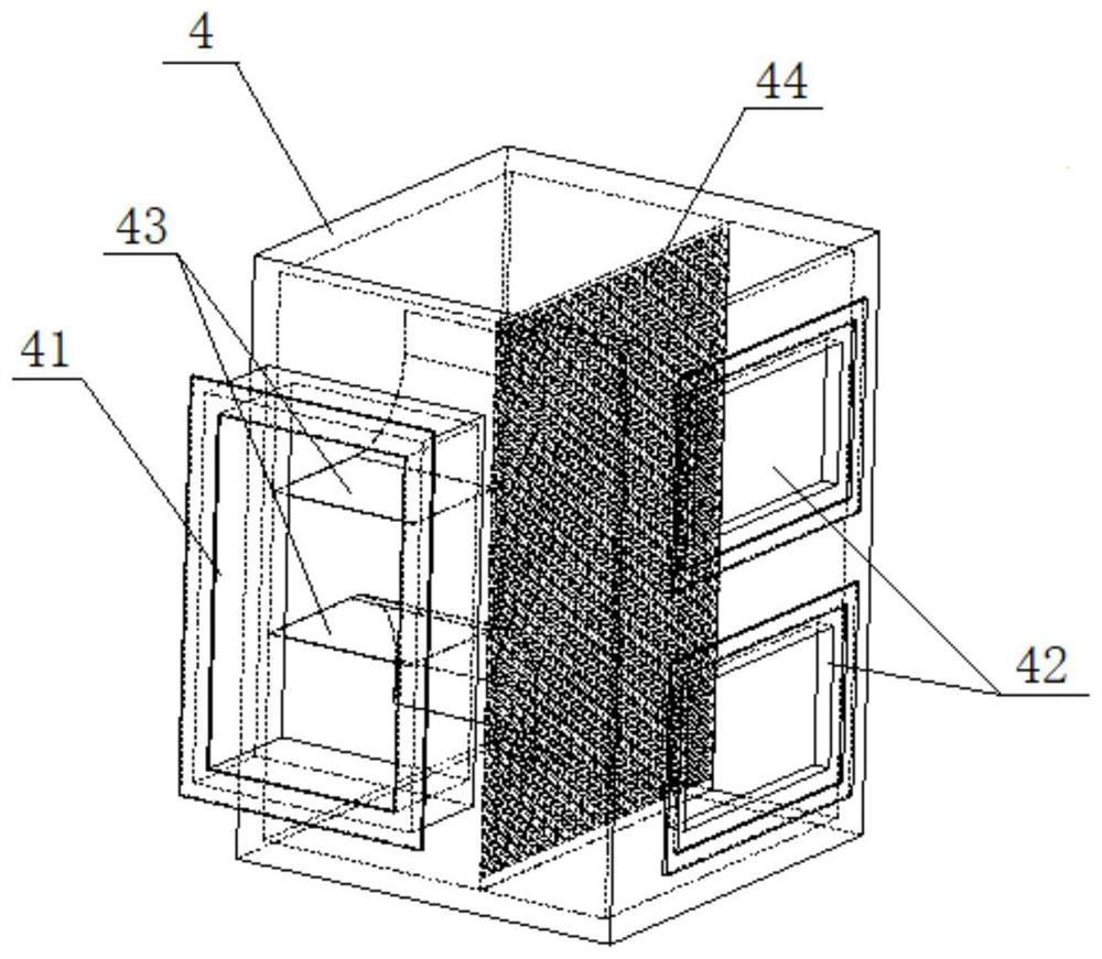
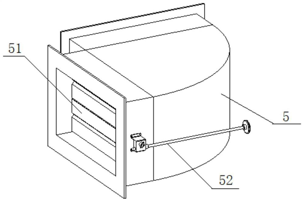
[0034] See Figure 1-Figure 6 , a uniform drying mechanism for a coating oven, comprising an oven body 1, an upper wind chamber 2 and a lower wind chamber 3 arranged in the oven casing 1, and an upper wind chamber 2 and a lower wind chamber 3 arranged outside the oven casing 1 and respectively connected to the upper wind chamber 2 and the lower wind chamber 3 Connected oven plenum box 4;

[0035] An air inlet 41 and an air outlet 42 are respectively provided ...


PUM


Abstract

The invention discloses a uniform drying mechanism of a coating oven. The uniform drying mechanism of the coating oven comprises an oven body, an upper air chamber, a lower air chamber and an oven static pressure chamber body, wherein the upper air chamber and the lower air chamber are arranged in the oven body; and the oven static pressure chamber body is arranged outside the oven body and respectively communicates with the upper air chamber and the lower air chamber. According to the uniform drying mechanism of the coating oven provided by the invention, through the primary steady flow air equalization of an oven static pressure chamber and the secondary steady flow air equalization of the upper air chamber and the lower air chamber, hot air blown out of the upper air chamber and the lower air chamber can evenly and rapidly dry two faces of a pole piece, so that the pole piece is ensured to be evenly heated; and the uniform drying mechanism of the coating oven is simple in structure,convenient to operate and reliable in operation.

Description

technical field [0001] The invention relates to the field of manufacturing lithium battery pole pieces, in particular to a coating oven uniform drying mechanism. Background technique [0002] In the production process of the existing power battery, the coating is mainly composed of two parts: coating and drying. The inertia of the airflow is relatively large, the airflow is unstable, and the uniformity of the hot air discharged from the air outlet of the tuyere is poor, resulting in uneven drying, wrinkling, and deviation of the pole pieces. In addition, most enterprises currently use high-efficiency and environmentally friendly suspension ovens instead of traditional roller ovens. The base material does not come into contact with the surface of the rollers, avoiding scratches on the surface of the pole piece inside the oven. The air nozzle structure of the floating oven used in the current market is mainly arranged vertically and staggeredly. The distance between the upper...

Claims


Application Information

Patent Timeline
Patent Type & Authority Applications(China)
IPC IPC(8): B05D3/04
CPCB05D3/0413
Inventor 李敏张旭何俊何曙邹宇程辉
Owner HEFEI GUOXUAN HIGH TECH POWER ENERGY
Learn More