
Clamping structure, spout welding device and laser welding device

A clamping structure and welding device technology, which is applied in laser welding equipment, welding equipment, welding equipment, etc., can solve problems such as clamping instability, and achieve the effects of good clamping stability, convenient operation, and accurate positioning

Pending Publication Date: 2020-11-10
中山市海德尔实业有限公司
View PDF0 Cites 1 Cited by
  • Summary
  • Abstract
  • Description
  • Claims
  • Application Information

AI Technical Summary

Problems solved by technology

[0003] The purpose of the embodiments of the present invention is to provide a clamping structure, aiming to solve the problem of unstable clamping

Method used


Image

  • Clamping structure, spout welding device and laser welding device
  • Clamping structure, spout welding device and laser welding device
  • Clamping structure, spout welding device and laser welding device

Examples


Embodiment Construction

[0028] In order to make the object, technical solution and advantages of the present invention clearer, the present invention will be further described in detail below in conjunction with the accompanying drawings and embodiments. It should be understood that the specific embodiments described here are only used to explain the present invention, not to limit the present invention.

[0029] The specific implementation of the present invention will be described in detail below in conjunction with specific embodiments.

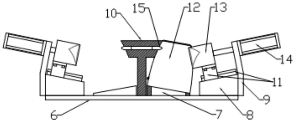
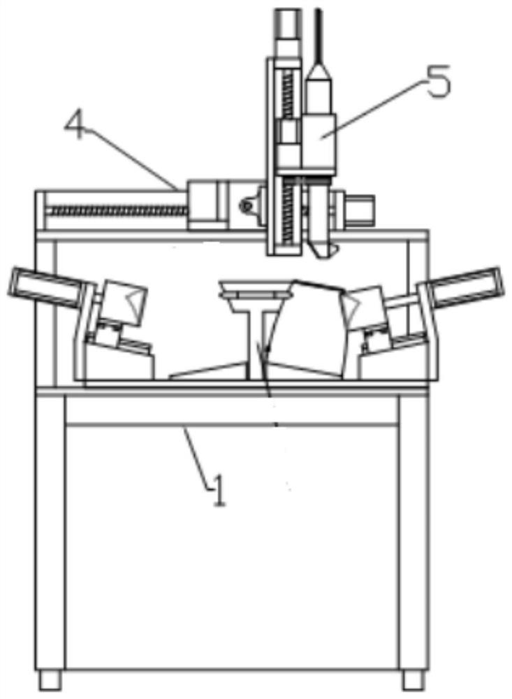
[0030] Such as Figure 1-2 As shown, it is a structural diagram of a clamping structure provided by an embodiment of the present invention, including:

[0031] The base 6 plays a supporting role;

[0032] The positioning seat 7 is installed on the base 6, and matches with the bottom of the kettle body 12 to support and position;

[0033] The positioning chuck 13, the clamping surface coincides with the spout, and is used to cooperate with the positioning seat ...


PUM


Abstract

The invention is applicable to the technical field of hardware machining and provides a clamping structure, a spout welding device and laser welding equipment. The clamping structure comprises a base,a positioning seat, a positioning chuck and a telescopic driving part. The base is used for supporting; the positioning seat is arranged on the base and is matched with the bottom of a kettle body toplay a role in supporting and positioning; the clamping surface of the positioning chuck is matched with the spout, and the positioning chuck is used for being matched with the positioning seat for clamping; and the telescopic driving part is connected with the positioning chuck and used for driving the positioning chuck to slide. The position of the spout of the kettle body is nested through thepositioning chuck, so that the positioning chuck is matched with the positioning seat to clamp the kettle body, the spout of the kettle body is matched with the positioning chuck, the kettle body isprevented from rotating, the kettle body can be positioned, and the steering position of the kettle body is determined; and the kettle body is prevented from sliding on the positioning seat through the positioning seat, and therefore the horizontal position of the kettle body is relatively fixed, and the positioning chuck and the positioning seat are matched to complete clamping of the kettle body. The clamping stability is good, operation is convenient and fast, positioning is accurate, and placing and taking are convenient and fast.

Description

technical field [0001] The invention belongs to the technical field of hardware processing, and in particular relates to a clamping structure, a spout welding device and laser welding equipment. Background technique [0002] With the development of society, people have entered a refined life, and kettles have entered thousands of households, and every household has a kettle. The kettle is an indispensable electrical appliance for every household, and the output of kettles has also increased by leaps and bounds. The spout of the kettle needs to be welded during the production process. The spout of the stainless steel kettle is usually welded by argon arc welding or butt welding, but the clamping is unstable during the welding process, which is likely to cause poor welding quality and the subsequent surface treatment process is equivalent. difficulty. Contents of the invention [0003] The purpose of the embodiments of the present invention is to provide a clamping structur...

Claims


Application Information

Patent Timeline
Patent Type & Authority Applications(China)
IPC IPC(8): B23K26/21B23K26/70B23K37/04
CPCB23K37/0443B23K26/21B23K26/702
Inventor 陈臻刘伟强
Owner 中山市海德尔实业有限公司
Learn More