
A printing device for textile fabrics and its working method

A textile fabric and printing technology, applied in the field of textile fabric printing equipment, can solve the problems of fabric contamination, fabric folds, low tension, etc., and achieve the effect of ensuring printing effect and uniform tension

Active Publication Date: 2022-04-19
桐乡市嘉灵新材料股份有限公司
View PDF0 Cites 0 Cited by
  • Summary
  • Abstract
  • Description
  • Claims
  • Application Information

AI Technical Summary

Problems solved by technology

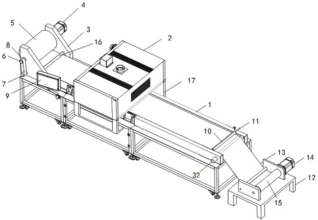
[0003] The purpose of the present invention is to provide a kind of printing equipment and its working method for textile cloth, which can solve the problem that when the traditional printing equipment is in use, the printing equipment only relies on the winding of the receiving roller to pull the cloth and discharge the material. Roller feeding, when the entire printing production line is long, it is easy to appear that the end of the cloth close to the receiving roller 15 has a large tension and tension, and the end far away from the end has a small and loose tension, resulting in poor printing effect. The fabric needs to be continuously conveyed. The traditional transmission method is to directly use the traction of the discharge roller and the collection roller to convey the textile fabric. When printing is required, stop the discharge roller and the collection roller, and use the printing parts to approach the textile fabric. And carry out printing. When the printing is completed, restart the feeding roller and the receiving roller. This method is easy to be affected by frictional resistance due to the direct contact between the cloth and the supporting base. Wrinkles appear in the moment of weaving the fabric. Secondly, when the inkjet printing part of the printing part has the problem of excessive spraying, the excess dye soaks through the fabric and contaminates the base. Since the position of the printing and dyeing area on the base is not fixed change, which will easily lead to the problem that the subsequent fabrics will also be contaminated during the continuous feeding process

Method used


Image

  • A printing device for textile fabrics and its working method
  • A printing device for textile fabrics and its working method
  • A printing device for textile fabrics and its working method

Examples


Embodiment Construction

[0027] The technical solutions of the present invention will be clearly and completely described below in conjunction with the embodiments. Apparently, the described embodiments are only some of the embodiments of the present invention, not all of them. Based on the embodiments of the present invention, all other embodiments obtained by persons of ordinary skill in the art without creative efforts fall within the protection scope of the present invention.

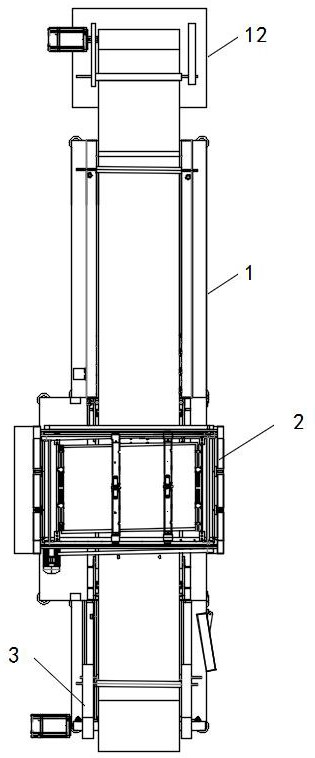
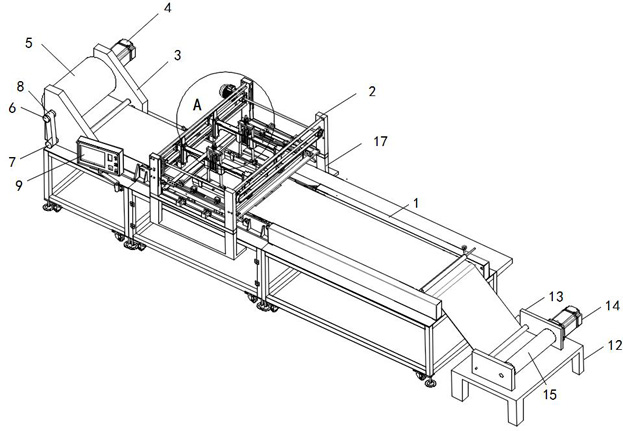
[0028] see Figure 1-5As shown, a printing device for textile fabrics includes a base 1, a discharge rack 3, a printing box 2, and a receiving rack 13. A conveyor belt is installed on the top of the base 1, and one end of the conveyor belt is socketed with the main transmission wheel 7. And the other end of the conveyor belt is socketed with the auxiliary transmission wheel 32, the discharge rack 3 is fixed on the top of one end of the base 1, and a discharge roller 5 is installed on the discharge rack 3, and one end of the...


PUM


Abstract

The invention discloses a printing device for textile fabrics, which comprises a base, a material discharging rack, and a printing box receiving rack. A conveyor belt is installed on the top of the base, and one end of the conveyor belt is sleeved with a main transmission wheel, and The other end of the conveyor belt is sleeved with the auxiliary conveyor wheel. It can solve the problem that when the traditional printing equipment is used, the end of the cloth close to the receiving roller is prone to high tension and tension, and the end far away from the end is weak and loose, resulting in poor printing effect. Secondly, the cloth is directly connected to the supporting base. When the material is stopped and the printing parts are close to the textile fabric due to the frictional resistance, the fabric will wrinkle. Secondly, when the inkjet printing part of the printing part has the problem of excessive spraying, the excess dye will soak into the fabric. Contamination on the base, since the position of the printing and dyeing area on the base is fixed, it is easy to cause the problem that subsequent fabrics will also be contaminated during the continuous feeding process.

Description

technical field [0001] The invention relates to the field of printing equipment, in particular to a printing equipment for textile cloth and a working method thereof. Background technique [0002] Printing equipment is a kind of textile tool. Printing equipment is used to print textile fabrics, so that textile fabrics are printed and dyed with required colors and patterns. However, existing printing equipment still has certain defects in use. First, printing equipment Only rely on the winding at the end of the receiving roller to pull the fabric and the discharging roller. When the entire printing production line is long, the tension at the end of the fabric close to the receiving roller is prone to be high and tight, and away from it. The tension at that end is small and loose, resulting in poor printing effect. Secondly, because the textile fabric needs to be continuously conveyed during the printing process, the traditional transmission method is to directly use the tract...

Claims


Application Information

Patent Timeline
Patent Type & Authority Patents(China)
IPC IPC(8): B65H16/06B65H16/10B65H18/10B65H20/06B65H20/02B65H20/10B65H23/185B65H23/192B41J3/407B41J11/00
CPCB65H16/06B65H16/103B65H18/103B65H20/06B65H20/02B65H20/10B65H23/185B65H23/192B41J3/4078B41J11/002B65H2701/174
Inventor 陈怡
Owner 桐乡市嘉灵新材料股份有限公司
Learn More