
Rib plate framework concrete cast-in-place slab

A concrete and cast-in-place slab technology, applied in the field of concrete cast-in-place slabs, can solve problems such as heavy workload, affecting project progress, and tediousness, and achieve the effects of improving bending bearing capacity, saving manpower and time, and improving structural strength

Inactive Publication Date: 2020-11-10
温伟斌
View PDF10 Cites 2 Cited by
  • Summary
  • Abstract
  • Description
  • Claims
  • Application Information

AI Technical Summary

Problems solved by technology

In the preparation process, it takes a lot of time to lay out the bottom formwork to form the construction work surface, and this part of the construction consumes a lot of manpower and time
In addition, the on-site reinforcement mesh binding also requires manual connection of the horizontal and vertical reinforcement bars with tie wires. The workload is heavy and cumbersome, which not only consumes a lot of manpower, but also seriously affects the progress of the project.
In the concrete cast-in-place slab structure with a large load, in order to increase the bending resistance of the structure, it is often necessary to equip steel bars with a larger diameter during design, resulting in an increase in cost

Method used


Image

  • Rib plate framework concrete cast-in-place slab
  • Rib plate framework concrete cast-in-place slab
  • Rib plate framework concrete cast-in-place slab

Examples


Embodiment 1

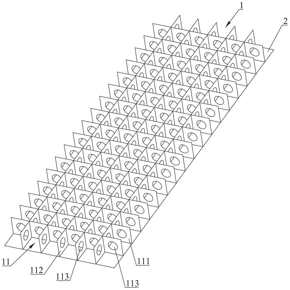
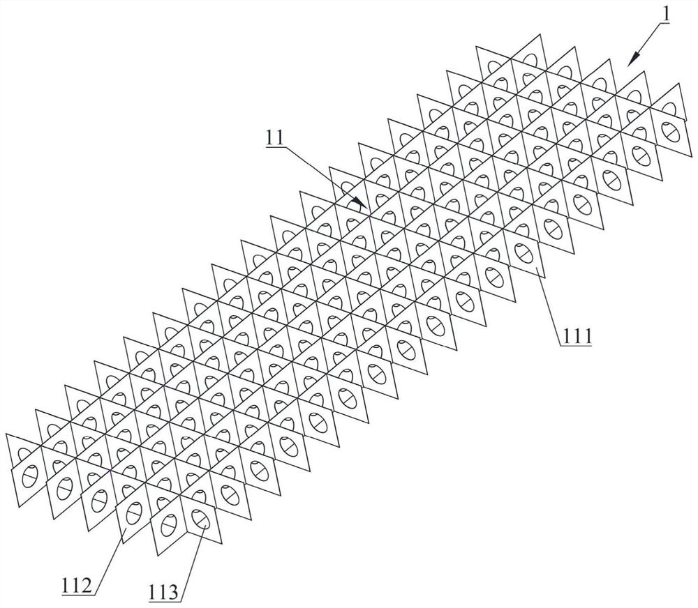
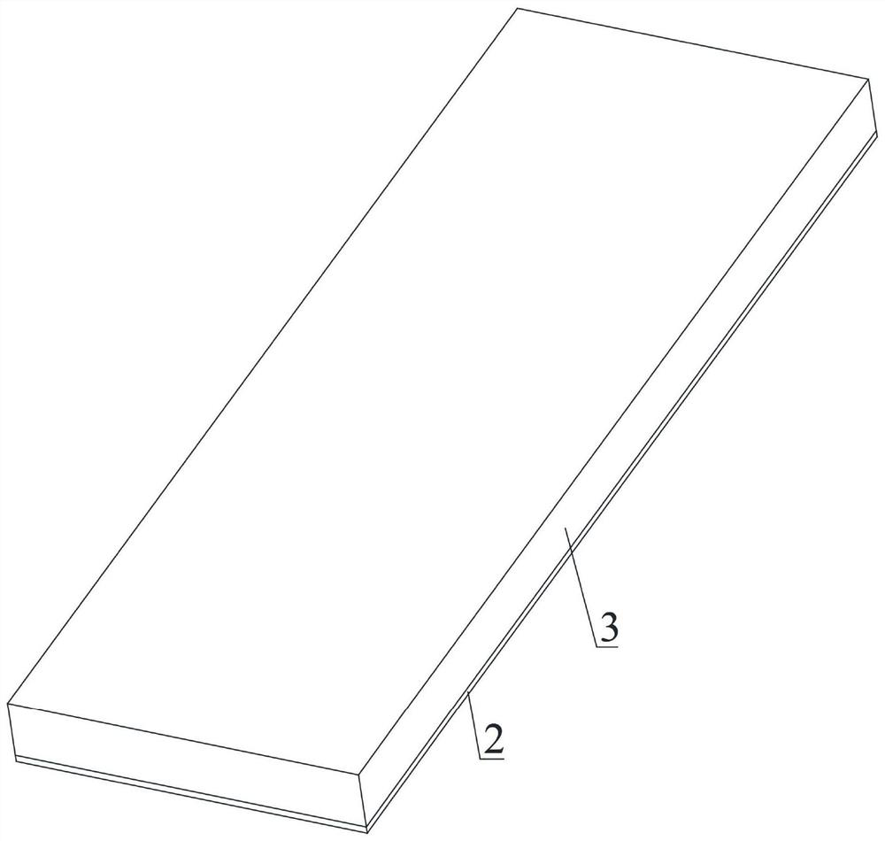
[0037] see Figure 1-3 As shown, the rib frame concrete cast-in-situ slab provided by the embodiment of the present invention includes a rib frame 1 , a bottom plate 2 and concrete 3 .

[0038] see figure 1 and figure 2 As shown, the rib frame 1 includes a plurality of transverse ribs 111 and a plurality of longitudinal ribs 112, wherein, in a preferred embodiment, the plurality of transverse ribs 111 are arranged in parallel and at intervals, and the plurality of longitudinal ribs 112 Parallel spacing between settings. A plurality of transverse ribs 111 and a plurality of longitudinal ribs 112 are criss-crossed to form a plurality of pouring units 11 . In some embodiments, the casting unit 11 may have a square cross section, that is, the distance between adjacent transverse ribs 111 is the same as the distance between adjacent longitudinal ribs 112 . There is a connecting channel 113 between adjacent casting units 11 to communicate with two adjacent casting units 11 , an...

Embodiment 2

[0047] see Figure 5 As shown, the second embodiment provides a more preferable connection structure between the transverse ribs 111 and the longitudinal ribs 112. In one embodiment, the lower side of the longitudinal ribs 112 is provided with a plurality of lower interlocking grooves 1121 at intervals. The distance between two adjacent lower interlocking grooves 1121 is the same as the distance between two corresponding adjacent transverse ribs 111, so that the two adjacent transverse ribs 111 can be inserted into two adjacent lower ribs. Embedding lock groove 1121 . The upper side of the transverse rib 111 is provided with a plurality of upper interlocking grooves 1111 at intervals, and the distance between two adjacent upper interlocking grooves 1111 is the same as the distance between the corresponding two adjacent longitudinal ribs 112 . The two adjacent longitudinal ribs 112 can be inserted into the two adjacent upper interlocking grooves 1111 .

[0048] In one embodim...

Embodiment 3

[0053] On the basis of any rib-skeleton concrete cast-in-place slab described in Embodiment 1 and Embodiment 2, this embodiment 3 provides a rib-skeleton concrete cast-in-situ slab with a connecting part 4, which is convenient for adjacent The connection between rib-frame concrete cast-in-place slabs or the connection between rib-frame concrete cast-in-place slabs and load-bearing beams. In one embodiment, see Figure 6 and Figure 7 As shown, a plurality of connecting parts 4 are arranged on the side of the rib-frame concrete cast-in-place slab, and after pouring concrete, at least a part of each connecting part 4 protrudes from the rib-plate skeleton concrete cast-in-place slab.

[0054] In some embodiments, the connection part 4 can be a structure such as a straight steel bar, a U-shaped steel bar, a straight-line plate or a U-shaped plate, and its uniform end is fixedly connected to the rib frame 1, and the other end protrudes from the rib frame to cast in-situ concrete. ...


PUM


Abstract

The invention relates to the technical field of concrete cast-in-place slabs, in particular to a rib plate framework concrete cast-in-place slab. The concrete cast-in-place slab comprises a rib plateframework, a bottom plate and concrete, wherein the rib plate framework comprises a plurality of criss-cross transverse rib plates and longitudinal rib plates to form a plurality of pouring units, a communication channel is formed between every two adjacent pouring units to communicate the two adjacent pouring units, the lower end of the rib plate framework is fixed to the bottom plate, and the pouring units are stuffed with concrete, cover the rib plate framework and are fixed to the bottom plate. According to the rib plate framework concrete cast-in-place slab, the bottom plate can be used as a bottom die, the time for arranging a bottom die is shortened, and manpower and time are saved. The rib plates are arranged in a staggered mode to form the rib plate framework, each rib plate is provided with a communication channel communicating with the adjacent pouring units, the rib plate framework is fixedly connected with the bottom plate, and therefore, the whole rib plate framework concrete cast-in-place slab has high bending resistance and bearing capacity.

Description

technical field [0001] The invention relates to the technical field of cast-in-place concrete slabs, in particular to a cast-in-place concrete slab with a rib plate skeleton. Background technique [0002] In civil engineering, traditional cast-in-place slabs consist of steel and concrete. During construction, the wooden formwork at the bottom is erected first, then steel bars are laid and bound on the working surface formed by the wooden formwork, and finally concrete is poured to form a concrete cast-in-place slab. In the preparation process, it takes a lot of time to lay out the bottom formwork to form the construction work surface, and this part of the construction consumes a lot of manpower and time. In addition, on-site binding of steel mesh also requires manual connection of horizontal and vertical steel bars with tie wires. The workload is heavy and cumbersome, which not only consumes a lot of manpower, but also seriously affects the progress of the project. In the ...

Claims


Application Information

Patent Timeline
Patent Type & Authority Applications(China)
IPC IPC(8): E04B5/32E04B5/40E04G11/48
CPCE04B5/32E04B5/40E04G11/48
Inventor 温伟斌黄方林冯帆陶勇曾文宋武段晟昱方岱宁
Owner 温伟斌
Learn More