Double-arm wall building robot and wall building method thereof
A wall-building robot and dual-arm technology, which is applied in construction, building structure, and building material processing, can solve the problems of large space and inconvenient operation, and achieve the effects of simplifying the wall-building process, preventing solidification, and high stability
- Summary
- Abstract
- Description
- Claims
- Application Information
AI Technical Summary
Problems solved by technology
Method used
Image
Examples
Embodiment 1
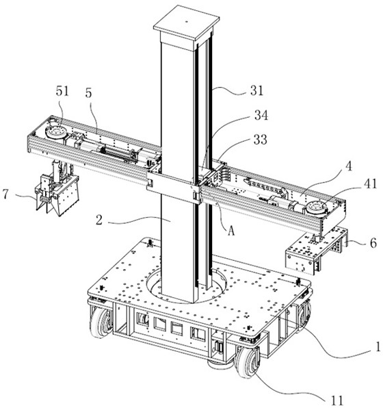
[0049] Such as figure 1 As shown, a dual-arm wall-laying robot includes a rotating base 1, a main body 2, a vertical movement module 3, a brick clamping arm 4, a pulp extraction arm 5, a first motor unit 41, a second motor unit 51, and a clamp 6 and pulp cup 7.
[0050] The main body 2 of the fuselage is arranged on the rotating base 1 , and the rotating base 1 is provided with a rotating motor (not shown in the figure), and the rotating motor controls the main body 2 to rotate 360 degrees along the rotating base 1 . The bottom of the rotating base 1 is provided with traveling wheels 11 to facilitate overall movement.
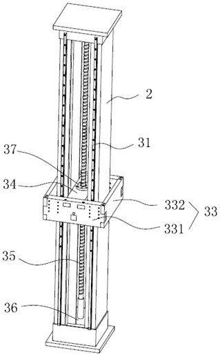
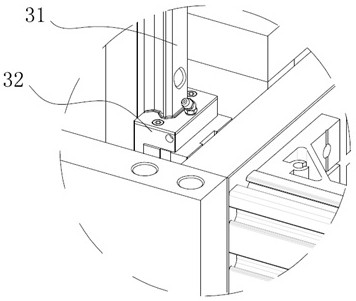
[0051] combine figure 2 , image 3As shown, the vertical movement module 3 is installed on the main body 2 of the fuselage. The vertical movement module 3 includes a guide rail 31 , a guide rail slider 32 , a sliding frame 33 , a lifting box 34 , a screw 35 , a screw motor 36 and a nut slider 37 . Guide rail 31 is fixed on the fuselage main body 2, and ...
Embodiment 2
[0056] Such as Figure 6-10 As shown, the dual-arm wall-laying robot of this embodiment also includes a multifunctional lifting device 8 on the basis of the first embodiment. The multifunctional hoisting device 8 comprises a brick transport frame 81, a slurry transport frame 82, a slurry bucket 83, a brick platform 84, two groups of movable pressing arm frames 85, four groups of tensioners 86 and two groups of diagonal tie rod assemblies. Brick transport frame 81 and pulp transport frame 82 are vertically installed on the rotating base 1 both sides, and brick transport frame 81 is provided with first vertical slide platform 811, and brick platform 84 is installed on the first vertical slide platform 811, transports The pulp rack 82 is provided with a second vertical slide table 821, and the pulp barrel 83 is installed on the second vertical slide table 821. Two groups of movable pressing arm frames 85 are respectively located above the brick transporting frame 81 and the slur...
Embodiment 3
[0074] Such as Figure 12-13 As shown, the difference between the present embodiment and the second embodiment is that the brick clamping arm 4 is fixedly mounted on the support plate 332, the pulp extraction arm 5 is fixedly mounted on the mounting plate 331, and the angle between the brick clamping arm and the pulp extraction arm is 90 degrees. angle.
[0075] Such as Figure 14 As shown, the brick transport frame 81 and the slurry transport frame 82 of the multifunctional lifting device 8 in this embodiment are set at an angle of 90 degrees corresponding to the brick clamping arm and the pulp extraction arm.
[0076] The wall-building method and the height adjustment method of the main body of the fuselage in this embodiment are the same as those in the second embodiment.
PUM
 Abstract
Description
Claims
Application Information
 - R&D
- Intellectual Property
- Life Sciences
- Materials
- Tech Scout
- Unparalleled Data Quality
- Higher Quality Content
- 60% Fewer Hallucinations
Browse by: Latest US Patents, China's latest patents, Technical Efficacy Thesaurus, Application Domain, Technology Topic, Popular Technical Reports.
© 2025 PatSnap. All rights reserved.Legal|Privacy policy|Modern Slavery Act Transparency Statement|Sitemap|About US| Contact US: help@patsnap.com


