Wind turbine generator

A technology for wind turbines and generators, which is applied to wind turbines, wind turbines at right angles to the wind direction, engines, etc., which can solve the problems of increasing costs, shortening the service life of generators, and high failure rates of generators, and achieving excellent cooling and heat dissipation. Excellent heat dissipation efficiency and the effect of accelerating air flow

Inactive Publication Date: 2020-11-10
滁州三界外工业设计有限公司
View PDF0 Cites 2 Cited by
  • Summary
  • Abstract
  • Description
  • Claims
  • Application Information

AI Technical Summary

Problems solved by technology

If the temperature in the winding becomes too high, the performance of the generator will be reduced. At the same time, when the generator set is in use, it will be fixed by external fixing equipment, and it will be fixed on the support base to ensure the working condition of the equipment. Stable operation, but the close fit of the external fixed equipment will cause the local part of the generator to be unable to ventilate and dissipate heat, resulting in high local temperature and affecting normal use. At the same time, in the prior art, the generator also lacks a good heat dissipation mechanism, resulting in The failure rate is high, which shortens the service life of the generator and increases the maintenance cost; 2. At the same time, during the normal driving operation of the wind turbine, the

Method used


Image

  • Wind turbine generator
  • Wind turbine generator
  • Wind turbine generator

Examples


Embodiment Construction

[0034] The technical solutions in the embodiments of the present invention will be clearly and completely described below in conjunction with the accompanying drawings in the embodiments of the present invention. Apparently, the described embodiments are only some, not all, embodiments of the present invention. Based on the embodiments of the present invention, all other embodiments obtained by persons of ordinary skill in the art without making creative efforts belong to the protection scope of the present invention.

[0035] see Figure 1 to Figure 9 , the present invention provides a technical solution:

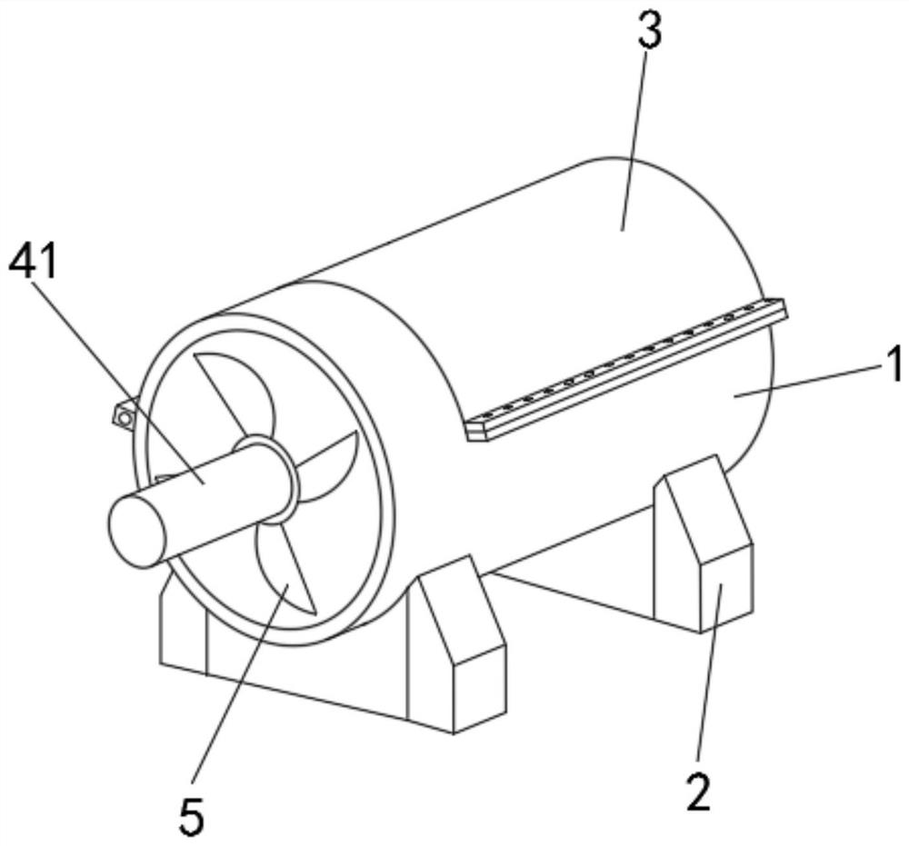
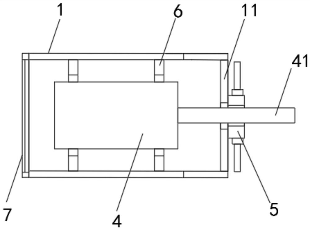
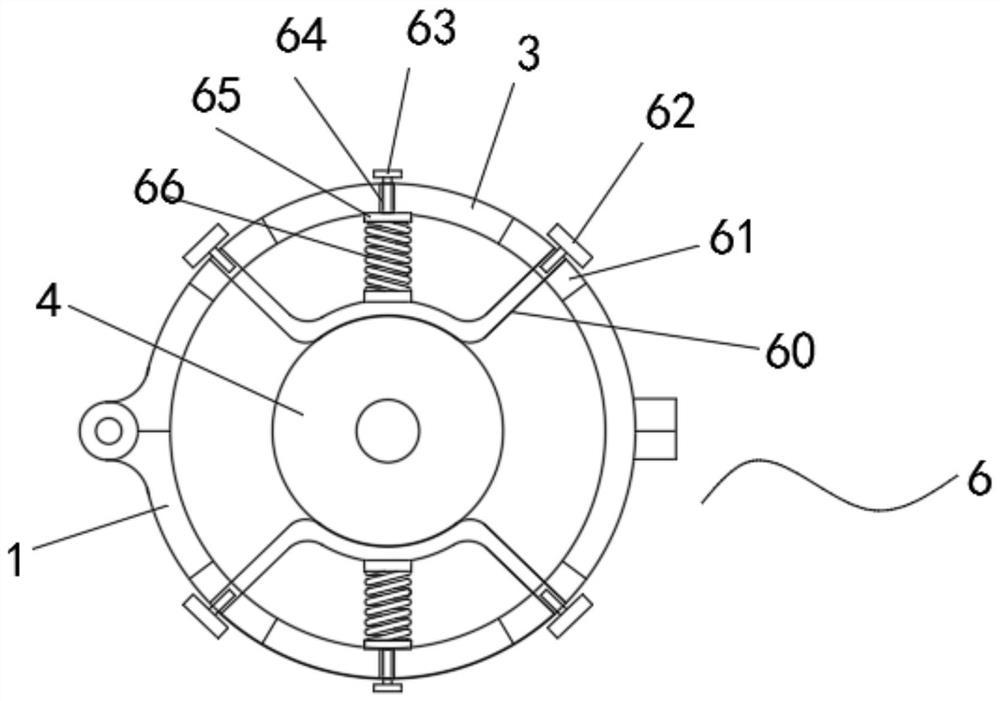
[0036] A wind turbine generator, comprising a main body of protective equipment 1, the outer surface of the lower end of the main body of the protective equipment 1 is symmetrically fixedly connected with supporting seats 2 on the front and rear sides, the outer surface of the upper end of the main body of the protective equipment 1 is provided with a The main body 1 coin...


PUM

PropertyMeasurementUnit
Fold angleaaaaaaaaaa

Abstract

The invention discloses a wind turbine generator. The wind turbine generator comprises a protective equipment main body; bearing seats are symmetrically and fixedly connected to the front side and therear side of the outer surface of the lower end of the protective equipment main body, a cover plate which is matched with the protective equipment main body is arranged on the outer surface of the upper end of the protective equipment main body, and the cover plate and the protective equipment main body are closed to form a complete hollow protective sleeve; and a generator main body is arrangedin the protective equipment main body, a vibration reduction clamping mechanism is arranged between the generator main body and the protective equipment main body, and three main connecting rods arefixedly connected to the position, close to the front end, in the protective equipment main body at equal intervals in an annular mode. According to the structure of the generator, through the arrangement of the protective equipment main body and the vibration reduction clamping mechanism which is used for clamping and fixing the generator main body, the wind turbine generator can be clamped and fixed by the vibration reduction clamping mechanism in the operation and use process, and the vibration amplitude generated by normal operation is buffered.

Description

technical field [0001] The invention relates to the technical field of turbine generators, in particular to a wind turbine generator. Background technique [0002] Wind turbine, referred to as fan or wind machine, converts the kinetic energy of the airflow into mechanical energy; this device is usually connected and drives a generator to generate electricity, which is one of the necessary conditions for a wind power plant. Wind generators are the foundation of modern science and technology. The product is a kind of power generation equipment that human beings use natural wind energy to convert the kinetic energy of the airflow into mechanical energy, and connect and drive the generator to generate electricity. [0003] In the process of realizing the present invention, the inventors found that at least the following problems in the prior art have not been solved: 1. During the long-term operation of the wind turbine, considerable heat is generated, the main heat source is in...

Claims


Application Information

Patent Timeline
IPC IPC(8): F03D80/60F03D80/00F03D3/06
CPCF03D3/062F03D80/00F03D80/60Y02E10/74
Inventor 任启兰许良云
Owner 滁州三界外工业设计有限公司
Why Eureka
Try Eureka