Main shaft brake mechanism based on magnetorheological fluid

A magneto-rheological fluid and braking mechanism technology, applied in the direction of braking actuators, gear transmission mechanisms, liquid resistance brakes, etc., can solve the problem of prolonging the braking time of the transmission spindle, increasing the rotational torque, friction and braking Shorten the deceleration and braking time, increase the cutting torque, and increase the braking torque to avoid problems such as small dynamic torque

Inactive Publication Date: 2020-11-10
许飚
View PDF12 Cites 4 Cited by
  • Summary
  • Abstract
  • Description
  • Claims
  • Application Information

AI Technical Summary

Problems solved by technology

[0005] The invention provides a spindle braking mechanism based on magnetorheological fluid, which has the advantages of large braking torque, no influence of centrifugal force on the braking torque and small power loss of the spindle during transmission, and solves the existing problems The brake disc of the brake mechanism based on magnetorheological fluid is immersed in the magnetorheological fluid. When the brake disc rotates with the transmission shaft at high speed, the centrifugal force and magnetic current generated by the high-speed rotation will be generated on the surface of the brake disc. A layer of gas film is formed between the variable fluids, so that when the magnetorheological fluid brakes after applying a magnetic field, the friction force and braking torque generated by the brake disc are small, thereby prolonging its braking time for the drive shaft , and because the brake disc is always immersed in the magneto-rheological fluid, there will be a certain fluid resistance between it and the magnetorheological fluid, which will increase the rotational torque of the drive shaft at startup and increase its speed during the transmission process. The problem of power loss

Method used


Image

  • Main shaft brake mechanism based on magnetorheological fluid
  • Main shaft brake mechanism based on magnetorheological fluid
  • Main shaft brake mechanism based on magnetorheological fluid

Examples


Embodiment Construction

[0020] The following will clearly and completely describe the technical solutions in the embodiments of the present invention with reference to the accompanying drawings in the embodiments of the present invention. Obviously, the described embodiments are only some, not all, embodiments of the present invention. Based on the embodiments of the present invention, all other embodiments obtained by persons of ordinary skill in the art without making creative efforts belong to the protection scope of the present invention.

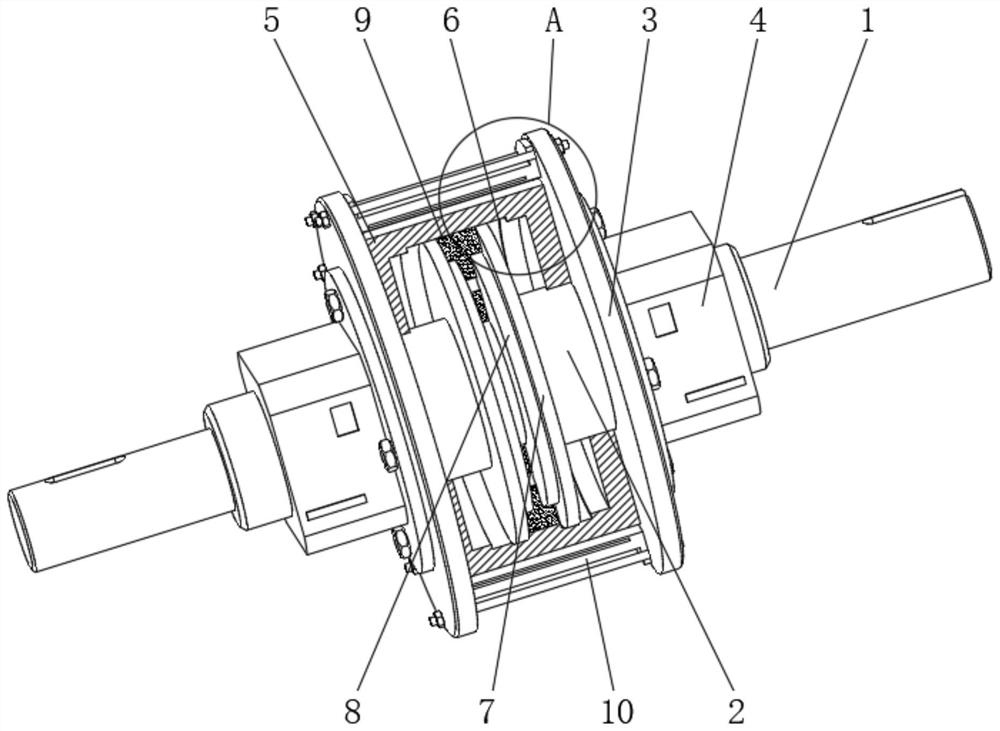
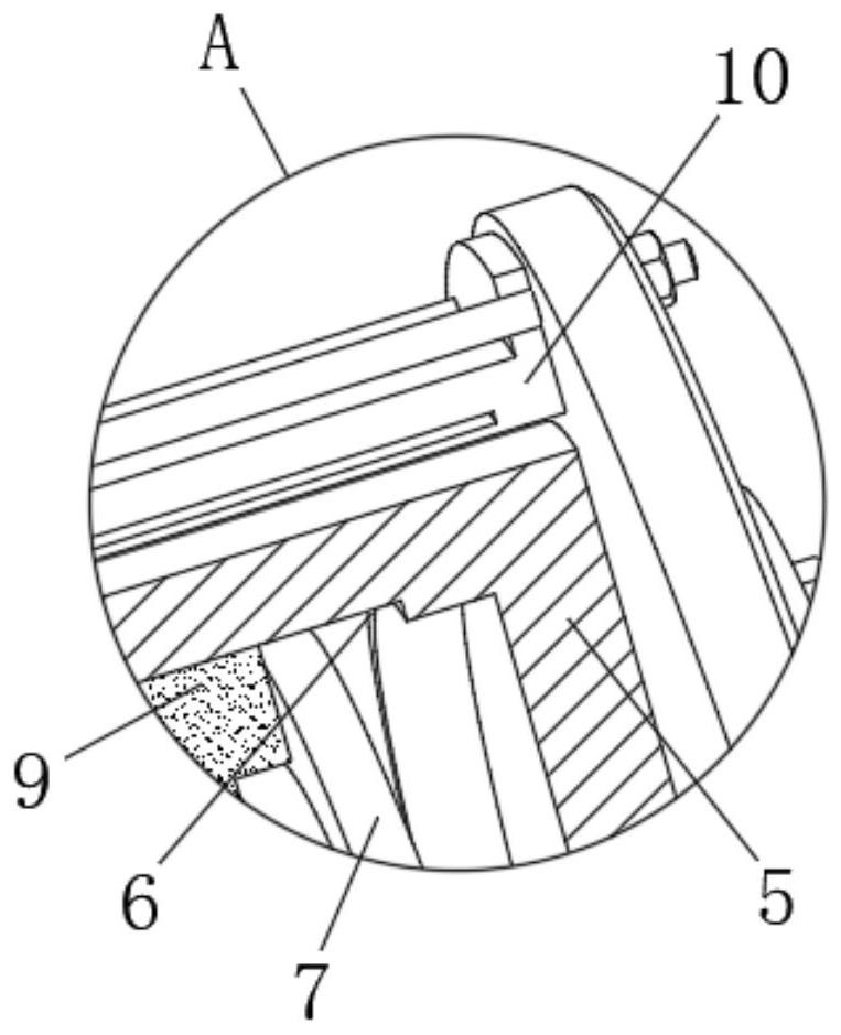
[0021] see Figure 1-3 , a main shaft brake mechanism based on magnetorheological fluid, comprising a transmission main shaft 1, both sides of the outer surface of the transmission main shaft 1 are movably fitted with a transmission spacer 2, and one side of the outer surface of the transmission spacer 2 is fixedly fitted with a connecting block Plate 3, and the outer side of the connecting baffle 3 is threadedly connected with the hydraulic mechanism 4, one e...


PUM


Abstract

The invention relates to the technical field of main shaft brake devices, and discloses a main shaft brake mechanism based on magnetorheological fluid. The main shaft brake mechanism comprises a transmission main shaft, wherein transmission spacer bushes movably sleeve two sides of the outer surface of the transmission main shaft, a connecting baffle plate fixedly sleeves one side of the outer surface of each transmission spacer bush, a hydraulic mechanism is in threaded connection with the outer side of each connecting baffle plate, one ends of the transmission spacer bushes is in transmission connection with the interiors of the hydraulic mechanisms, brake shells are fixedly installed on the inner sides of the connecting baffle plates, and intercepting grooves are formed in the inner walls of the brake shells. According to the main shaft brake mechanism based on the magnetorheological fluid, due to the arrangement of an intercepting through hole and the inclination angle of the intercepting through hole, the tangent angle of the intercepting through hole to the magnetorheological fluid can be increased, and therefore braking of the transmission main shaft is achieved not only through friction between the surface of the intercepting through hole and the magnetorheological fluid; and meanwhile, the cutting torque of the magnetorheological fluid is increased by utilizing the intercepting through hole, so that the braking torque generated by the main shaft brake mechanism during braking is further increased.

Description

technical field [0001] The invention relates to the technical field of spindle braking devices, in particular to a spindle braking mechanism based on magnetorheological fluid. Background technique [0002] As a new type of intelligent material, magnetorheological fluid can change its rheological properties rapidly and continuously with the change of the applied magnetic field, and presents a low-viscosity, high-fluidity Newtonian fluid in the absence of a magnetic field. characteristics, but in a strong magnetic field, it exhibits a high viscosity, low fluidity, solid-like characteristics, and there is a stable correspondence between its viscosity and magnetic field. Therefore, based on the magnetorheological fluid under the action of a magnetic field characteristics, using the strong shear yield strength generated by it, can effectively regulate the rotational torque of the transmission spindle, and then realize the continuous control of the speed of the transmission spindl...

Claims


Application Information

Patent Timeline
Patent Type & Authority Applications(China)
IPC IPC(8): F16D57/00F16D65/14F16D121/18
CPCF16D57/002F16D65/14F16D2121/18
Inventor 许飚
Owner 许飚
Why Eureka
Try Eureka