Skid-mounted hydrogenation device for new energy automobile

A technology for new energy vehicles and hydrogenation devices, applied in motor vehicles, road vehicles, transportation and packaging, etc., can solve the problems of inconvenient transportation, unfavorable product investment recovery, large floor space, etc., and achieves simple and efficient operation and use. and the effect of enhanced use, easy transportation and installation

Inactive Publication Date: 2020-11-10
SICHUAN DIWEI ENERGY TECH
View PDF6 Cites 6 Cited by
  • Summary
  • Abstract
  • Description
  • Claims
  • Application Information

AI Technical Summary

Problems solved by technology

[0004] The main purpose of the present invention is to provide a skid-mounted hydrogenation device for new energy vehicles to solve the problem that the current hydrogenation stations are all fixed and single, inconvenient to transport, occupy a large area, and are not suitable for overall relocation. Long cycle, high civil construction cost investment, long on-site commissioning cycle of hydrogen refueling station, which is not conducive to the investment recovery of the whole set of products, etc.

Method used


Image

  • Skid-mounted hydrogenation device for new energy automobile
  • Skid-mounted hydrogenation device for new energy automobile
  • Skid-mounted hydrogenation device for new energy automobile

Examples


Embodiment 1

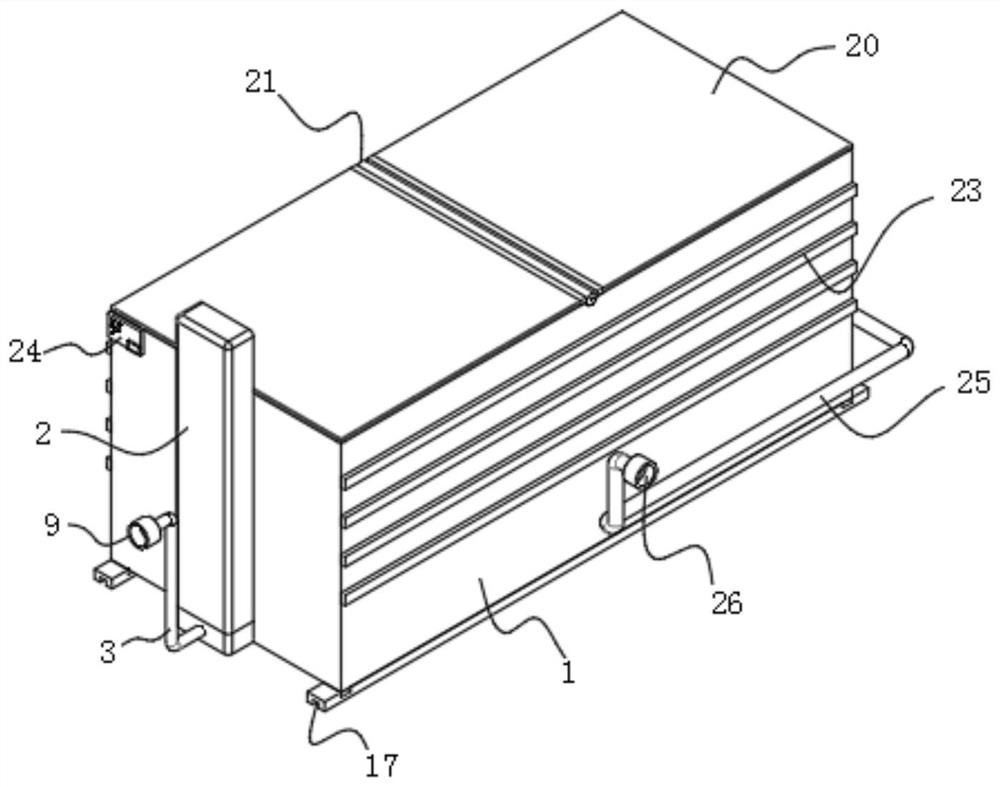
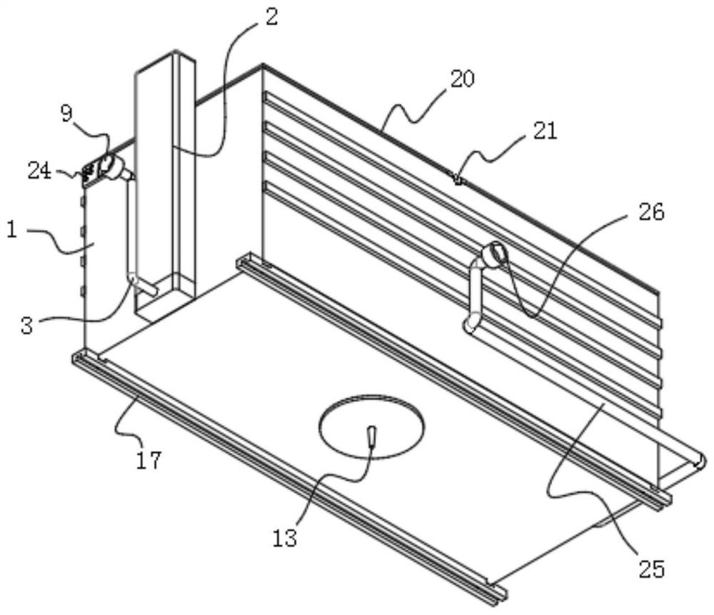
[0029] Please refer to Figure 1-7 Shown: a skid-mounted hydrogenation device for new energy vehicles, including a box 1, a hydrogen unloading column 2 and a second hydrogenation pipe 25, a hydrogen unloading column 2 is installed on one side of the box 1, and the hydrogen unloading column 2 The output end is connected to the box body 1, the second hydrogenation pipe 25 is installed on the other side of the box body 1, and the first hydrogen storage tank 4, the second hydrogen storage tank 5 and the third hydrogen storage tank 6 are respectively arranged inside the box body 1 A cold air pipeline 16 is connected between the first hydrogen storage tank 4 and the second hydrogen storage tank 5, the second hydrogen storage tank 5 and the third hydrogen storage tank 6, and a compressor 7 is installed on one side of the first hydrogen storage tank 4 , the output end of the compressor 7 is connected with a cooler 8, the output end of the cooler 8 is connected with the cold air pipeli...

Embodiment 2

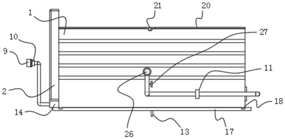
[0031] Please refer to Figure 1-7 As shown: the outer surfaces of the first hydrogen storage tank 4, the second hydrogen storage tank 5 and the third hydrogen storage tank 6 are connected with the first hydrogenation pipe 15, and the combined use of the two sets of hydrogenation pipes can improve the hydrogenation of the hydrogen storage tank. Adaptability, according to the actual use requirements, carry out separate hydrogenation or integrated operation, the first hydrogenation pipe 15 side is connected to the second solenoid valve 12, the second hydrogenation pipe 25 side is connected to the first solenoid valve 11, Independent self-adaptive control is performed on the hydrogenation pipe. The grounding pin 13 is connected to the bottom of the box body 1 to improve the electrostatic protection effect and enhance safety. The bottom end of the box body 1 is equipped with an installation slider 17. There is a buffer post 18 connected between the cabinets 1, and the slider 17 is...

Embodiment 3

[0034]It should be noted that the present invention is a skid-mounted hydrogenation device for new energy vehicles. During operation and use, the long hydrogen tube vehicle is connected to the hydrogen unloading column 2 through the gas unloading pipeline 3, and the hydrogen unloading column 2 uses a meter 14 After metering, it is compressed by the compressor 7 and stored in the first hydrogen storage tank 4, the second hydrogen storage tank 5 and the third hydrogen storage tank 6 respectively, wherein the first hydrogen storage tank 4 is a high-pressure tank and the second hydrogen storage tank 5 is a medium-pressure tank, and the third hydrogen storage tank 6 is a low-pressure tank, which fills each gas storage tank group in sequence according to the high, medium and low-pressure tank groups, and the stored hydrogen passes through the first hydrogenation pipe 15 and the second hydrogenation pipe 25. Fill the vehicle. When filling the hydrogenation pipe, take gas from the tube...


PUM


Abstract

The invention discloses a skid-mounted hydrogenation device for a new energy automobile, and relates to the technical field of hydrogenation equipment. The skid-mounted hydrogenation device comprisesa box body, a hydrogen unloading column and a second hydrogenation pipe, the hydrogen unloading column is installed at one side of the box body, the output end of the hydrogen unloading column is connected with the box body, and the second hydrogenation pipe is installed at the other side of the box body; a first hydrogen storage tank, a second hydrogen storage tank and a third hydrogen storage tank are arranged in the box body, cold air pipelines are connected between the first hydrogen storage tank and the second hydrogen storage tank and between the second hydrogen storage tank and the third hydrogen storage tank, a compressor is installed at one side of the first hydrogen storage tank, the output end of the compressor is connected with a cooler, and the output end of the cooler is connected with the cold air pipelines; and one surface of the hydrogen unloading column is connected with a gas unloading pipeline, and the input end of the gas unloading pipeline is connected with a gasinlet. According to the integrated skid-mounted hydrogenation device, key equipment is systematically integrated, transportation and installation are more convenient, and integrated and intelligent design and manufacturing of hydrogen refueling station equipment and application of the Internet of Things are achieved.

Description

technical field [0001] The invention relates to the technical field of hydrogenation equipment, in particular to a skid-mounted hydrogenation device for new energy vehicles. Background technique [0002] With the increasing global warming problem and the encouragement of national policies for the development and utilization of hydrogen energy, more and more hydrogen energy vehicles are put on the market. The hydrogen energy market urgently needs to provide complete supporting hydrogen refueling facilities for hydrogen energy vehicles, hydrogen refueling stations As a necessary supporting implementation, it also emerged as the times require. In view of the current land market conditions where every inch of land is expensive, skid-mounted, integrated, safe and reliable hydrogen refueling stations are more suitable for the hydrogen energy equipment market; [0003] The current hydrogen refueling stations are all fixed and single-unit hydrogen refueling stations. Although these ...

Claims


Application Information

Patent Timeline
Patent Type & Authority Applications(China)
IPC IPC(8): F17C1/00F17C5/06F17C13/04F17C13/00
CPCF17C1/00F17C5/06F17C13/04F17C13/00F17C2223/0123F17C2250/03F17C2270/0178Y02E60/32
Inventor 陈超刘全文曾加金杨桂荣胡翔宇
Owner SICHUAN DIWEI ENERGY TECH
Why Eureka
Try Eureka