
A Displacement Measuring Device and Method Based on Electromagnetically Induced Transparent Atom Grating
An electromagnetically induced transparency and displacement measurement technology, applied to measuring devices, optical devices, instruments, etc., can solve problems such as cost increase, repeated adjustment system complexity, measurement errors, etc., achieve high displacement measurement accuracy, and reduce production process requirements , the effect of low integration difficulty
Patent Information
- Authority / Receiving Office
- CN · China
- Patent Type
- Patents(China)
- Current Assignee / Owner
- Publication Date
- 2021-05-14
Smart Images
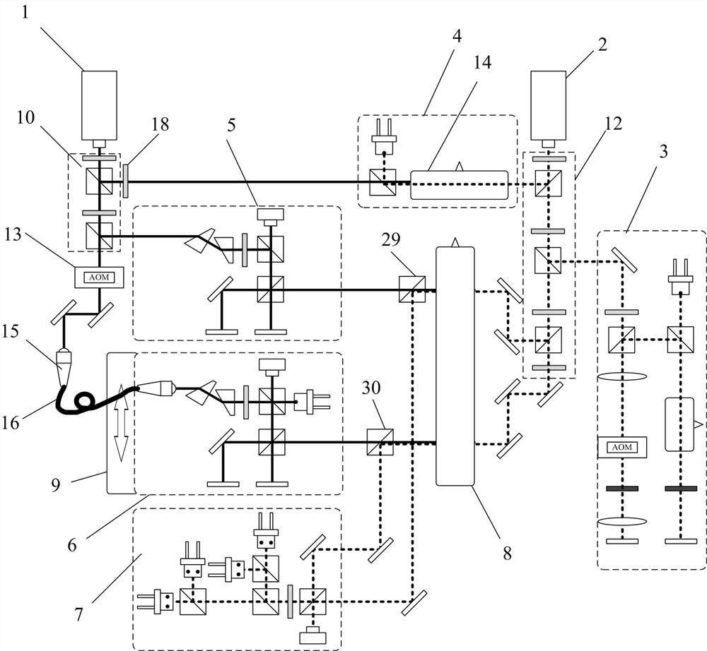
Figure 1 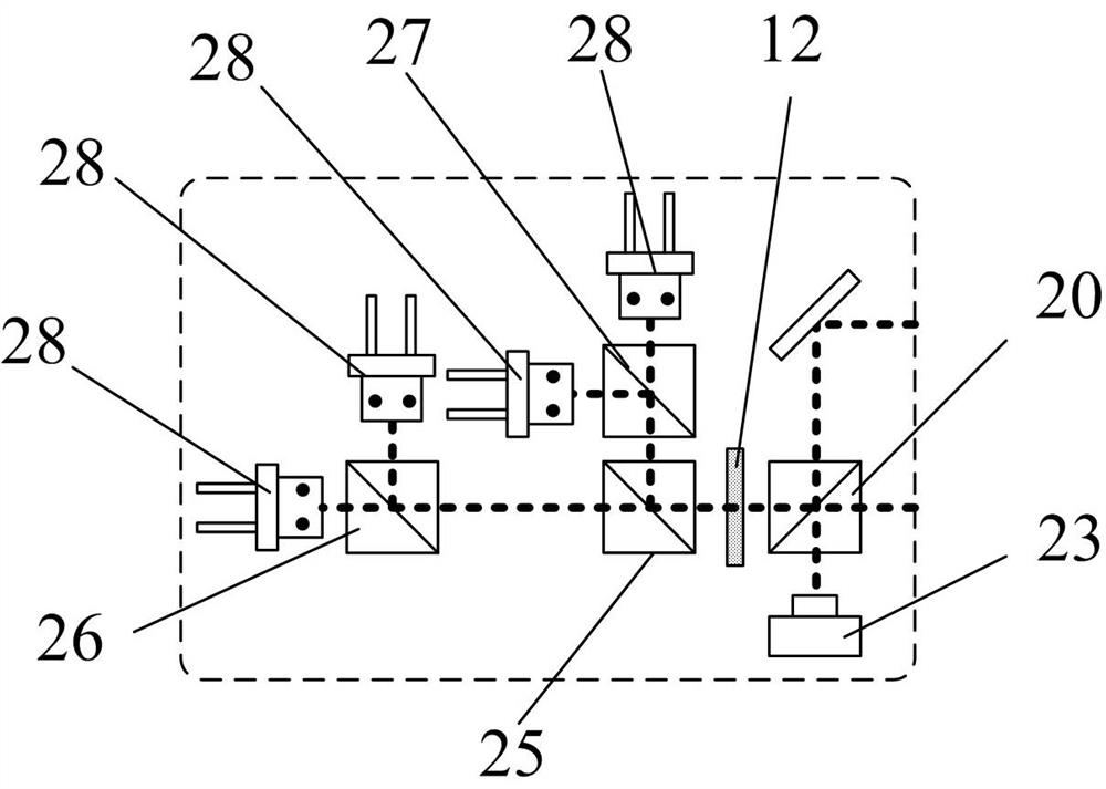
Figure 2 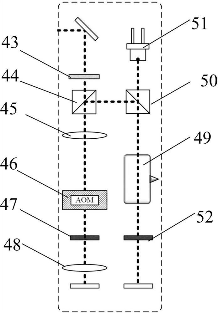
Figure 3
Abstract
Description
technical field
[0001] The invention belongs to the technical field of precision displacement measurement, and in particular relates to a displacement measurement device and method based on an electromagnetically induced transparent atomic grating. Background technique
[0002] The grating displacement measurement technology first used the Moiré fringe phenomenon formed by the grating overlap to realize the precise measurement of displacement, but the grating based on this measurement principle is only suitable for occasions that do not require high precision. Later, with the development of grating displacement measurement technology based on the principle of interferometry, the accuracy of grating displacement measurement has been improved to the nanometer level, and it has been applied in cutting-edge equipment such as lithography machines. However, the traditional grating displacement measurement technology is mainly based on the physical grating. The grating manufacturin...
Examples
Embodiment Construction
[0039] In order to make the purpose, technical solutions and advantages of the embodiments of the present invention clearer, the technical solutions in the embodiments of the present invention will be clearly and completely described below. Obviously, the described embodiments are part of the embodiments of the present invention, rather than All the embodiments; based on the embodiments of the present invention, all other embodiments obtained by persons of ordinary skill in the art without making creative efforts all belong to the protection scope of the present invention.
[0040] like figure 1 As shown, the embodiment of the present invention provides a displacement measurement device based on an electromagnetically induced transparent atomic grating, including a coupling laser source 1, a detection laser source 2, an offset frequency-locked optical path 3, an electromagnetically induced frequency-locked optical path 4, and a reference interference optical path 5. Measure th...