High extinction ratio light delay regulation and control structure and device

A technology of optical delay and extinction ratio, which is applied in optics, nonlinear optics, instruments, etc., can solve the problems of low extinction and leakage of optical delay structures, and achieve the effects of meeting delay requirements, reducing noise, and high extinction ratio

Pending Publication Date: 2020-11-10
THE 44TH INST OF CHINA ELECTRONICS TECH GROUP CORP
View PDF8 Cites 0 Cited by
  • Summary
  • Abstract
  • Description
  • Claims
  • Application Information

AI Technical Summary

Problems solved by technology

The traditional optical delay control structure is generally an optical switch in series with optical transmission paths of different lengths. However, due to the limitation of the preparation process of the optical switch itself, there is often leaked light in addition to the signal light, which will lead to optical delays. The extinction ratio of the delay structure is relatively low, and the leaked light will be superimposed continuously during the transmission process. When the number of series delay optical paths is large, the impact of the leaked light is particularly serious

Method used


Image

  • High extinction ratio light delay regulation and control structure and device
  • High extinction ratio light delay regulation and control structure and device
  • High extinction ratio light delay regulation and control structure and device

Examples


Embodiment 1

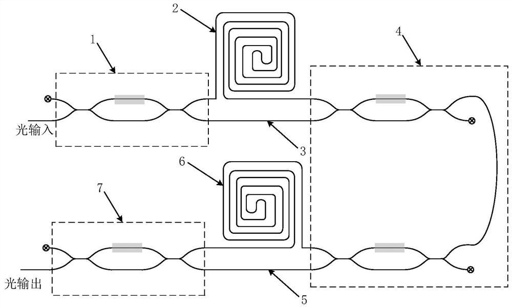
[0024] Such as figure 2 As shown, a preferred embodiment of the high extinction ratio optical delay control structure of the present invention includes an input optical switch 1, a first optical waveguide delay line 2, a first optical waveguide straight-through line 3, a high extinction ratio optical switch 4, a second The optical waveguide delay line 5, the second optical waveguide straight-through line 6 and the output optical switch 7, the input optical switch 1, the high extinction ratio optical switch 4 and the output optical switch 7 are all provided with two input terminals and two output terminals , both the input optical switch 1 and the output optical switch 7 are preferably Mach-Zehnder optical switches.

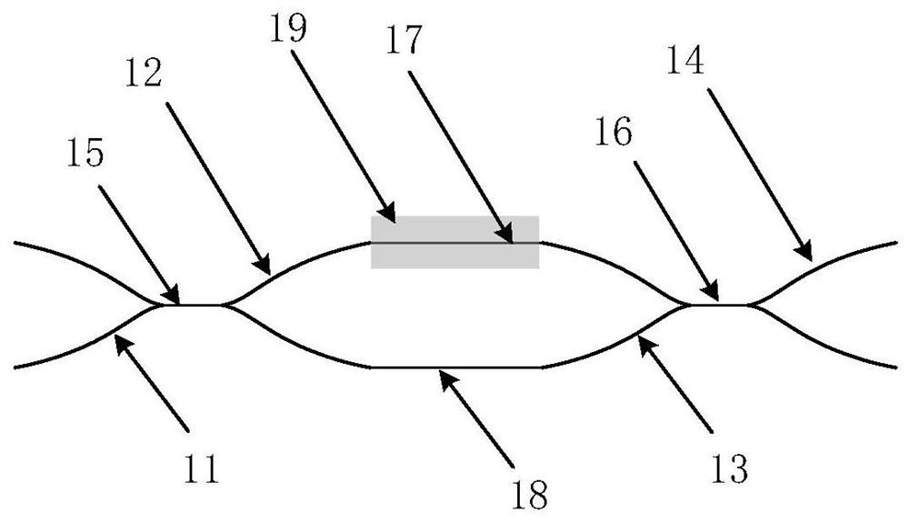
[0025] Such as image 3 As shown, the Mach-Zehnder optical switch includes a first Y-branch waveguide 11, a first straight waveguide 15, a second Y-branch waveguide 12, an upper interference arm 17, a lower interference arm 18, a third Y-branch waveguide 13, a s...

Embodiment 2

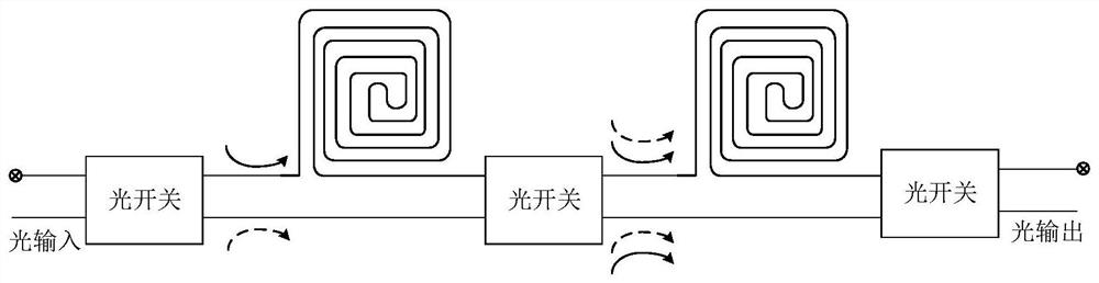
[0036] A high extinction ratio light delay control device, comprising N high extinction ratio light delay control structures in Embodiment 1, N is a natural number greater than 1; the N high extinction ratio light delay control structures are connected in series connect. Such as Figure 5 As shown, connecting the output terminal of a high extinction ratio optical delay control structure to the input terminal of another high extinction ratio optical delay control structure can realize the series connection of two control structures ( Figure 5 In each dotted box is a high extinction ratio light delay control structure), similarly, a series connection of multiple high extinction ratio light delay control structures can also be realized. Using the high extinction ratio optical delay control structure in Example 1 as a basic unit of the optical delay control device, the control range of the optical delay can be increased by connecting multiple optical delay control structures in ...


PUM


Abstract

The invention discloses a high extinction ratio optical delay regulation and control structure, which comprises an input optical switch, a first optical waveguide delay line, a first optical waveguidestraight line, a high extinction ratio optical switch, a second optical waveguide delay line, a second optical waveguide straight line and an output optical switch; the high extinction ratio opticalswitch comprises two mach-zehnder optical switches; and one output end of the first Mach-Zehnder optical switch is connected with one input end of the second Mach-Zehnder optical switch. According tothe invention, the optical waveguide delay line and the optical waveguide straight-through line are connected in series by adopting the double Mach-Zehnder optical switches, the first Mach-Zehnder optical switch enables signal light and leakage light in an optical path to be transmitted separately, then the leakage light in the optical path is effectively filtered, and the second Mach-Zehnder optical switch controls the transmission path selection of the optical path. Regulation and control of an optical path are achieved, so that the extinction ratio in an optical link is improved, and the noise in the optical link is reduced.

Description

technical field [0001] The invention relates to the field of light delay control, in particular to a high extinction ratio light delay control structure and device. Background technique [0002] As an important optical control device, the variable optical delay line is widely used in scientific research and practical engineering. In the field of optical signal transmission, the delay control technology of optical signal is the key technology in analog signal transmission. The common method is to realize the delay control of light by adjusting different transmission paths of light. With the development of economy and technology, people The delay control of optical signals puts forward higher and higher requirements, such as: ultra-fast, high extinction ratio, high precision, wide range, etc. [0003] Such as figure 1 As shown, the current optical delay control structure is to connect delay optical paths of different lengths in series through multiple optical switches, and s...

Claims


Application Information

Patent Timeline
Patent Type & Authority Applications(China)
IPC IPC(8): G02F1/225G02F1/313
CPCG02F1/2257G02F1/0147G02F1/3136
Inventor 庾财斌肖永川瞿鹏飞孙力军
Owner THE 44TH INST OF CHINA ELECTRONICS TECH GROUP CORP
Why Eureka
Try Eureka