Search circuit
A search circuit and binary search technology, applied in the field of search circuits, can solve the problems of increased installation area and complex processor control.
- Summary
- Abstract
- Description
- Claims
- Application Information
AI Technical Summary
Problems solved by technology
Method used
Image
Examples
no. 1 example
[0049]
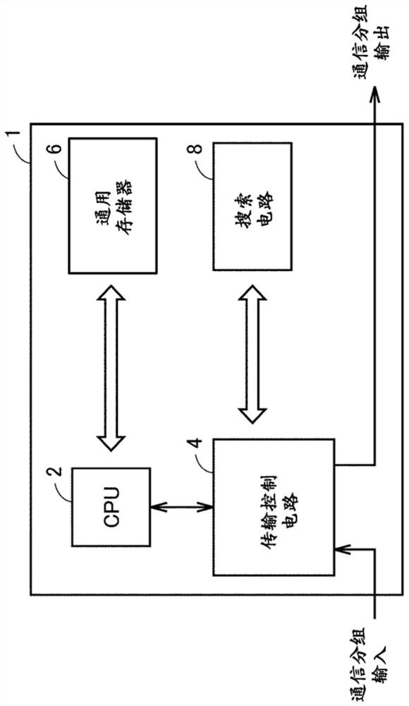
[0050] figure 1 is a diagram showing the configuration of the communication device 1 according to the first embodiment.
[0051] like figure 1 As shown, the communication device 1 is a communication device such as a switch or a router. The communication device 1 is connected to the Internet. The communication device 1 performs transmission processing of packet data.
[0052] The communication device 1 includes a central processing unit (central processing unit) 2 , a transmission control circuit 4 , a general-purpose memory 6 , and a search circuit 8 .
[0053] CPU 2 controls the entire device. The CPU 2 realizes various functions in cooperation with programs stored in the general-purpose memory 6 . For example, the general-purpose memory 6 can be configured with DRAM (Dynamic Random Access Memory), and construct an operating system (OS) by cooperating with the CPU 2 . The CPU 2 exchanges information with adjacent communication devices and the like, and main...
no. 2 example
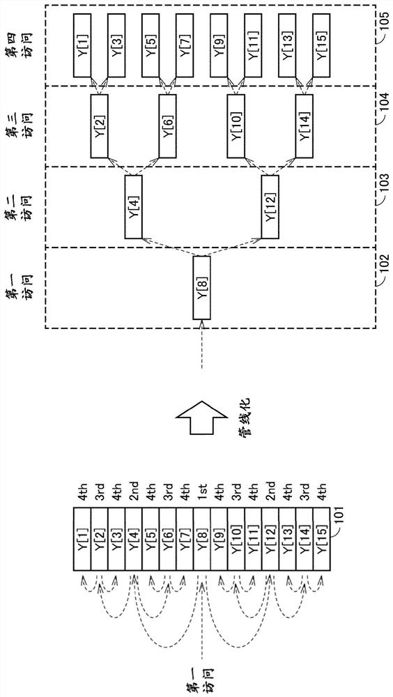
[0200] In the first embodiment described above, the entry data is divided into two groups, and the entry data of the first group stored in the plurality of built-in memories 503 and the entry data of the second group stored in the memory 506 are separated. The remaining entry data other than the first group are divided into a plurality of sub-entry data groups grouped according to stages of eight search stages corresponding to the number of banks. The entry data of each sub-entry data group BLK is sequentially stored in the memory bank BANK corresponding to each search stage.
[0201] In this case, as Figure 6 As shown, the capacity used by the storage bank corresponding to the previous search phase is 1 / 2 of the capacity used by the storage bank corresponding to the subsequent search phase. Therefore, when a plurality of banks are all designed to have the same capacity, there is a larger unused capacity since it becomes the bank corresponding to the previous search stage. ...
no. 3 example
[0220] In the third embodiment, a method of using the capacity of the memory more efficiently will be described.
[0221] Figure 17 is a diagram for explaining the outline of a search algorithm for binary search according to the third embodiment.
[0222] refer to Figure 17 , the search circuit according to the third embodiment includes a processor 1101 and a memory 1106 .
[0223] The processor 1101 includes a plurality of first processing units 1102-1 to 1102-(K-8), a plurality of built-in memories 1103-1 to 1103-(K-8), a second processing unit 1104, and a An interface circuit 1105 for exchanging data between the unit 1104 and the memory 1106 . The plurality of first processing units 1102-1 to 1102-(K-8) have the same functions as the plurality of first processing units 502-1 to 502-(K-8) of the first embodiment, and their descriptions are omitted .
[0224] Then, the determination result of the first processing unit 1102 -(K-8) is output to the second processing unit...
PUM
 Abstract
Description
Claims
Application Information
 - R&D
- Intellectual Property
- Life Sciences
- Materials
- Tech Scout
- Unparalleled Data Quality
- Higher Quality Content
- 60% Fewer Hallucinations
Browse by: Latest US Patents, China's latest patents, Technical Efficacy Thesaurus, Application Domain, Technology Topic, Popular Technical Reports.
© 2025 PatSnap. All rights reserved.Legal|Privacy policy|Modern Slavery Act Transparency Statement|Sitemap|About US| Contact US: help@patsnap.com


