High-voltage power cabinet with good heat dissipation effect

A technology of high-voltage power and heat dissipation effect, applied in the direction of electrical components, substation/power distribution device shell, substation/switch layout details, etc., can solve the problems of cabinet temperature rise, power cabinet open flame, heat dissipation process troubles, etc., to increase Air flow rate, good transmission performance, good ventilation effect

Active Publication Date: 2020-11-10
广东中盛纳科技有限公司
View PDF14 Cites 1 Cited by
  • Summary
  • Abstract
  • Description
  • Claims
  • Application Information

AI Technical Summary

Problems solved by technology

[0003] For hot areas and high-voltage power cabinets with many power components inside the power cabinet, although the power cabinet can dissipate heat, the power components inside the power cabinet will generate more heat during long-term use. If the heat dissipation is not timely It is easy to cause the internal temperature of the cabinet to rise, thereby affecting the operation of the power cabinet, and in more serious cases, it will cause an open flame in the power cabinet
However, the heat dissipation process of the existing high-voltage power cabinet is cumbersome, and fans are usually used for heat dissipation, and the heat dissipation effect is not satisfactory. Therefore, a high-voltage power cabinet with good heat dissipation effect is proposed to solve the above problems

Method used


Image

  • High-voltage power cabinet with good heat dissipation effect
  • High-voltage power cabinet with good heat dissipation effect
  • High-voltage power cabinet with good heat dissipation effect

Examples


Embodiment Construction

[0021] The following will clearly and completely describe the technical solutions in the embodiments of the present invention with reference to the accompanying drawings in the embodiments of the present invention. Obviously, the described embodiments are only some, not all, embodiments of the present invention. Based on the embodiments of the present invention, all other embodiments obtained by persons of ordinary skill in the art without making creative efforts belong to the protection scope of the present invention.

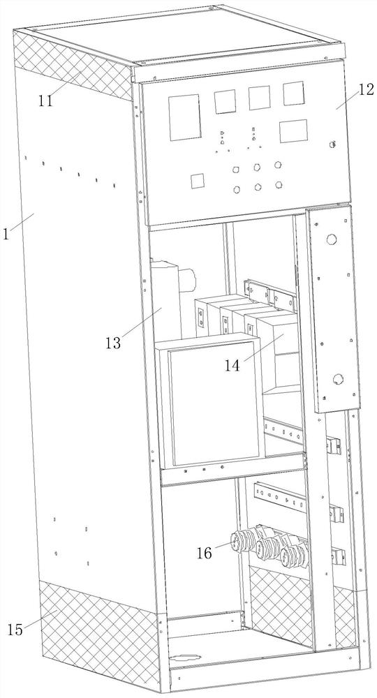
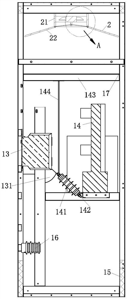
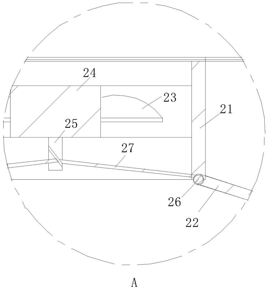
[0022] see Figure 1-7 As shown, a high-voltage power cabinet with good heat dissipation effect includes a cabinet body 1, a PLC controller 12 is fixed on the upper side wall of the cabinet body 1, and an air intake cover 11 is arranged above the two side walls of the cabinet body 1 , an exhaust hood 15 is arranged below the two side walls of the cabinet body 1, a lightning arrester 16 is installed inside the cabinet body 1, a short circuit protector 13 is ins...


PUM

PropertyMeasurementUnit
Rotation angleaaaaaaaaaa

Abstract

The invention relates to the technical field of power cabinets, in particular to a high-voltage power cabinet with a good heat dissipation effect. The cabinet comprises a cabinet body, a PLC is fixedon the upper side wall of the cabinet body, air inlet hoods are arranged above the two side walls of the cabinet body, and air exhaust hoods are arranged below the two side walls of the cabinet body;air can be conveniently fed through the arranged air inlet hoods when a draught fan rotates, the air inlet hoods are arranged on the side walls of the cabinet body, dust can be prevented from enteringthe cabinet body, and water drops can be prevented from entering the cabinet body from the air inlet hoods at the top of the cabinet body when moisture regaining occurs to the cabinet body. The arranged exhaust hoods can exhaust air flowing from the top out of the cabinet body, circulation of air in the cabinet body is ensured, an arranged heat dissipation mechanism can rapidly blow air into thecabinet body, and when the heat dissipation mechanism carries out exhausting, the air speed in the cabinet body can be changed, so the heat dissipation effect of the cabinet body is improved; therefore, the air flowing speed in the cabinet body can be changed, and the ventilation effect of the cabinet body is better.

Description

technical field [0001] The invention relates to the technical field of power cabinets, in particular to a high-voltage power cabinet with good heat dissipation effect. Background technique [0002] The power cabinet is the final equipment of the power distribution system. The power distribution cabinet is a general term for the motor control center. The power distribution cabinet is used in the occasions where the load is relatively scattered and there are few circuits; the motor control center is used in the occasions where the load is concentrated and there are many circuits. They distribute the electric energy of a certain circuit of the upper-level power distribution equipment to the nearest load. This level of equipment shall provide protection, monitoring and control of the load. [0003] For hot areas and high-voltage power cabinets with many power components inside the power cabinet, although the power cabinet can dissipate heat, the power components inside the po...

Claims


Application Information

Patent Timeline
IPC IPC(8): H02B1/56H02B1/30H02B1/32H02B1/052
CPCH02B1/565H02B1/30H02B1/32H02B1/052
Inventor 不公告发明人
Owner 广东中盛纳科技有限公司
Why Eureka
Try Eureka